Eureka AIR delivers breakthrough ideas for toughest innovation challenges, trusted by R&D personnel around the world.

Microwave dielectric ceramic material, preparation method and application thereof, and filter ceramic material

A technology of microwave dielectric ceramics and ceramic materials, which is applied in the field of filter ceramic materials, can solve the problems of low dielectric constant, high insertion loss, and the dielectric constant needs to be improved, and achieves the effect of high dielectric constant and low loss value.

Active Publication Date: 2019-11-22
福建省德化县华瓷新材料科技有限公司
View PDF8 Cites 2 Cited by
  • Summary
  • Abstract
  • Description
  • Claims
  • Application Information

AI Technical Summary

Problems solved by technology

[0003] At present, the dielectric constant of microwave dielectric ceramic materials is low, and the insertion loss is high, which cannot meet people's needs. The method of improving microwave dielectric ceramic materials in the prior art is usually to research and develop new materials. The dielectric constant of microwave dielectric ceramic materials is still To be improved, the loss value still needs to be reduced

Method used


Image

  • Microwave dielectric ceramic material, preparation method and application thereof, and filter ceramic material
  • Microwave dielectric ceramic material, preparation method and application thereof, and filter ceramic material
  • Microwave dielectric ceramic material, preparation method and application thereof, and filter ceramic material

Examples


preparation example Construction

[0047] In the present invention, the preparation method of the E component preferably includes the following steps:

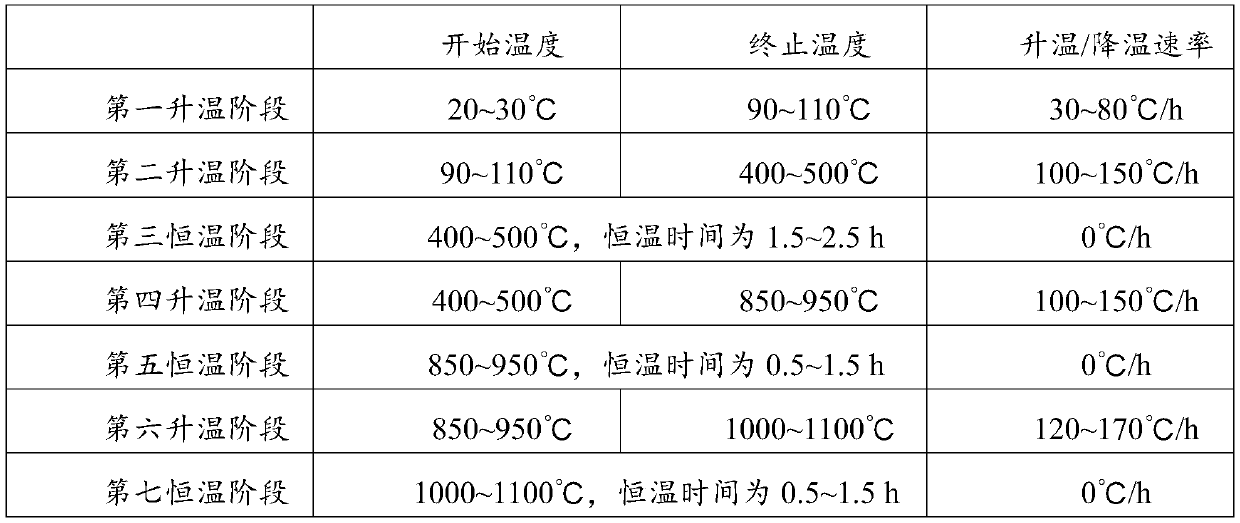
[0048] Mix silicon oxide, calcium oxide and magnesium oxide, perform sintering treatment, and then cool to obtain flux; the sintering treatment includes 7 stages in sequence, specifically the first heating stage, the second heating stage, and the third constant temperature stage , the fourth heating stage, the fifth constant temperature stage, the sixth heating stage, the seventh constant temperature stage; the cooling treatment includes two stages carried out in sequence, including the first cooling stage and the second cooling stage; the sintering treatment and cooling The specific parameters of the processing are shown in Table 1:

[0049] Table 1 Sintering treatment and cooling treatment parameters when preparing component E

[0050]

[0051] In the present invention, the sintering treatment and cooling treatment parameters when preparing the E componen...

Embodiment 1-1

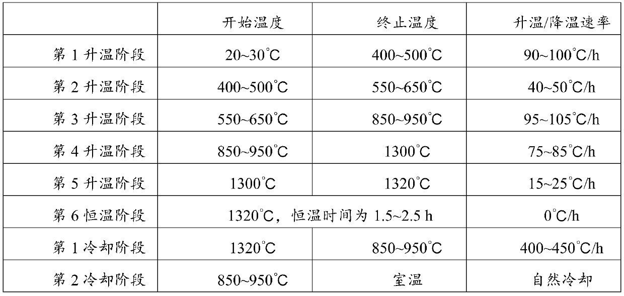
[0100] Mix A component, B component, C component, D component and E component, where A component is BaTi 4 o 9 , the mass fraction of A component is 65%; B component is Ba 2 Ti 9 o 20 , the mass fraction of component B is 24%, component C is BaWO 4 , the mass fraction of component C is 0.2%, and component D is ZnTiO 3 , SnTiO 3 、LaTiO 3 , NdTiO 3 、BaSm 2 Ti 4 o 12 and PrTiO 3 a mixture of ZnTiO in the D component 3 , SnTiO 3 、LaTiO 3 , NdTiO 3 、BaSm 2 Ti 4 o 12 and PrTiO 3 The mass ratio of the component is 26.3:24.7:16:16:8.2:8.8; the mass fraction of the D component is 0.8%, the E component is a flux, and the mass fraction of the E component is 10%, and the preparation method of the E component is : CaO, MgO and SiO 2 The mixture is sequentially sintered and cooled to obtain the E component, the SiO 2 The mass ratio of , CaO and MgO is 10:3:1. The sintering and cooling process is as follows: from room temperature to 100°C, the heating rate is 50°C / h; fro...

Embodiment 1-2

[0105] Mix A component, B component, C component, D component and E component, wherein the ingredients of A component, B component, C component, D component and E component are the same as in Example 1-1 Similarly, the mass fractions of component A, component B, component C, component D and component E are 66%, 23%, 2.3%, 0.7% and 8% in sequence.

[0106] Then, according to the method of Example 1-1, components A, B, C, D and E were mixed, ball milled, granulated, pressed, fired and cooled to obtain a microwave dielectric ceramic material.


PUM

PropertyMeasurementUnit
thicknessaaaaaaaaaa
frequency temperature coefficientaaaaaaaaaa

Abstract

The invention provides a microwave dielectric ceramic material, a preparation method and application thereof, and a filter ceramic material, and belongs to the technical field of electronic materials.The microwave dielectric ceramic material provided in the invention includes, by mass, a component A, a component B, a component C, a component D and a component E, wherein the component A is BaTi4O9, the component B is Ba2Ti9O20, the component C is BaWO4, the component D is a mixture of ZnTiO3, SnTiO3, LaTiO3, NdTiO3, BaSm2Ti4O12 and PrTiO3, and the component E is obtained by sintering and cooling CaO, MgO and SiO2 in sequence. The microwave dielectric ceramic material provided by the invention is relatively high in dielectric constant, small in dielectric loss, relatively high in quality factor Q and relatively small in frequency temperature coefficient.

Description

technical field [0001] The invention relates to the technical field of electronic materials, in particular to a microwave dielectric ceramic material, a preparation method and application thereof, and a filter ceramic material. Background technique [0002] Microwave dielectric ceramic materials refer to ceramic materials that are used as dielectric materials in microwave frequency circuits and perform one or more functions. As a new type of electronic material, microwave dielectric ceramics are used as resonators, filters, dielectric substrates, dielectric antennas, and dielectric waveguide circuits in modern communications. With the high-end development of microwave communication equipment, digital audio-visual, satellite communication, and military radar, the requirements for microwave dielectric ceramic materials are also increasing. [0003] At present, the dielectric constant of microwave dielectric ceramic materials is low, and the insertion loss is high, which canno...

Claims


Application Information

Patent Timeline
Patent Type & Authority Applications(China)
IPC IPC(8): C04B35/468C04B35/622
CPCC04B35/468C04B35/622C04B2235/3232C04B2235/326C04B2235/3206C04B2235/3208C04B2235/3418C04B2235/602C04B2235/656C04B2235/6562C04B2235/6567C04B2235/6565
Inventor 林福文林友荣林信浔李建民
Owner 福建省德化县华瓷新材料科技有限公司
Why Eureka
Eureka Blog
Learn More