
Wideband dual-circularly polarized microstrip-to-waveguide feeding source antenna system

An antenna system and circular waveguide technology, applied in the field of broadband dual circularly polarized 77GHz microstrip-to-waveguide feed antenna system, can solve the problems of easy generation of high-order modes, reduction of antenna gain, low robustness, etc., and achieve reduction The generation of high-order modes, the reduction of coupling effects, and the effect of reducing coupling interference

Pending Publication Date: 2019-07-16
MICROCREATIVE TECH CO LTD
View PDF0 Cites 8 Cited by
  • Summary
  • Abstract
  • Description
  • Claims
  • Application Information

AI Technical Summary

Problems solved by technology

[0003] The early radar technology was mainly based on pulse radar technology, but pulse radar technology has obvious disadvantages: for example, the transmission power requirement is very large, the transmission and reception needs to be switched, there are detection blind spots, the volume is large, and it is easy to be intercepted, etc.
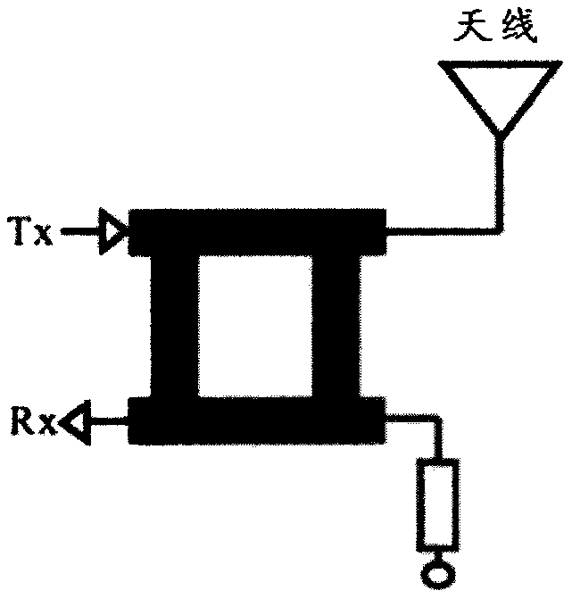
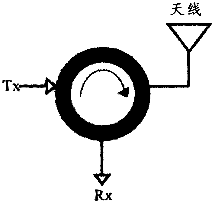
[0006] However, the inventor found through research that in the circulator solution, the characteristics of the ferrite material will change dramatically in the 77GHz frequency band, so it is difficult to implement it using PCB technology
In the dual-antenna solution, one antenna is used for reception and transmission; theoretically, as long as the two antennas are far enough apart, the isolation can be very good; but as a product design, two antennas are bound to be required Double the space; especially in the 77GHz radar design, in order to achieve a longer communication distance, the size of the antenna is larger, and the two antennas will inevitably occupy a larger space, making the product structure more bloated
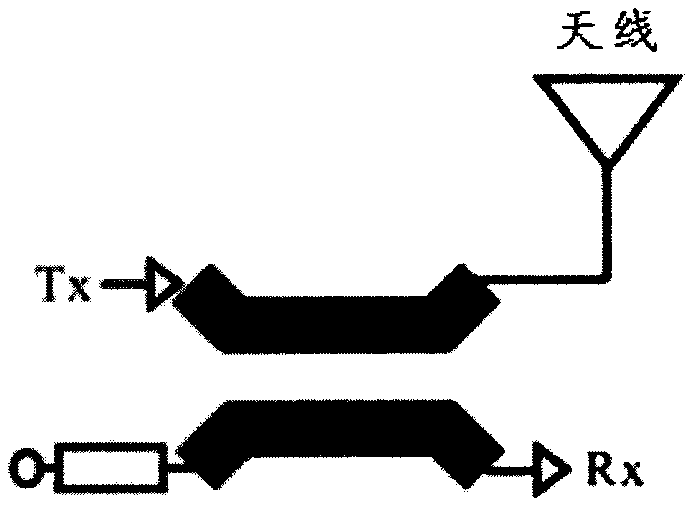
Therefore, in the prior art, circulators or dual antennas are used in order to achieve transceiver isolation. The circulator will cause the gain loss of the antenna, and the dual antenna system will increase the size of the antenna, and it will also cause the antenna to lose its directivity. gain loss
[0007] Since the receiving end and the transmitting end of FMCW radar work at the same time, the antenna mostly uses a linearly polarized antenna, which results in poor isolation between the receiving and transmitting ports and affects the performance of the antenna.
To solve this problem, a circulator can be added to improve the isolation of the transceiver port, but the circulator will bring additional attenuation and reduce the sensitivity of the antenna; or, different antennas are used at the transceiver end, but this method will cause Increase the size of the device and reduce the antenna gain due to directivity problems
[0008] see figure 2 As shown, in the prior art, the scheme of rectangular-circle conversion is often used for microstrip-to-waveguide conversion. Due to the symmetry of the circular waveguide, there is a phenomenon of polarization degeneracy, which will excite various modes, and the discontinuity of the circular waveguide will be more It is easy to excite higher-order modes; and because the main mode TE10 mode of the rectangular waveguide is very similar to the main mode TE11 mode of the circular waveguide, through figure 2 The rectangular conversion structure shown can realize mode conversion well and reduce the generation of high-order modes, so it has better working performance; but figure 2 The scheme shown breaks the circular symmetry and cannot generate circularly polarized waves
As shown in Figure 3, in the prior art, the depth of the short-circuit piston is often adjusted for impedance matching through the excitation method of the microstrip probe, so that the energy coupled into the circular waveguide can be maximized; however, in the scheme in Figure 3 It is necessary to add a short-circuit piston, which brings certain difficulties to its processing design in the 77GHz millimeter-wave frequency band, and because it is directly converted from the microstrip to the circular waveguide, it is very easy to generate high-order modes, and its working bandwidth cannot reach the system. design requirements
[0009] In the prior art, the microstrip antenna usually uses a single-layer patch direct excitation method, which is simple in design and processing, but the working bandwidth is narrow, usually less than 5%, and the robustness is not high due to the narrow bandwidth , is easily restricted by machining accuracy, and cannot realize broadband design

Method used


Image

  • Wideband dual-circularly polarized microstrip-to-waveguide feeding source antenna system
  • Wideband dual-circularly polarized microstrip-to-waveguide feeding source antenna system
  • Wideband dual-circularly polarized microstrip-to-waveguide feeding source antenna system

Examples


Embodiment Construction

[0035] The following will clearly and completely describe the technical solutions in the embodiments of the present invention with reference to the accompanying drawings in the embodiments of the present invention. Obviously, the described embodiments are only some, not all, embodiments of the present invention. Based on the embodiments of the present invention, all other embodiments obtained by persons of ordinary skill in the art without creative efforts fall within the protection scope of the present invention.

[0036] The invention discloses a high-isolation, wide-band, microstrip-to-waveguide feed antenna system working in the 77GHz frequency band.

[0037] see Figure 4 , 5 As shown, the antenna system 1 includes a bridge 2, an upper metal ground 3, an upper substrate 4, a lower substrate 5, a lower metal ground 6, a radiation patch 7, a mode converter 8, a circular waveguide 9, and a metal via 10;

[0038] see Figure 5 The side view of the antenna system 1 is shown...


PUM


Abstract

The invention discloses an antenna system. The antenna system comprises an electric bridge, upper-layer metal ground, an upper-layer substrate, a lower-layer substrate, lower-layer metal ground, a radiation patch, a mode converter, a circular waveguide and a metal via hole, wherein the antenna system is of a multi-layer plate structure sequentially comprising the upper-layer metal ground, the upper-layer substrate, the lower-layer substrate and the lower-layer metal ground from top to bottom, the radiation patch is arranged at an upper side of the upper-layer substrate, the mode converter is arranged on the radiation patch and is connected to the circular waveguide on the radiation patch, the electric bridge forms a feeding network, and two ports of the electric bridge are arranged betweenthe upper-layer substrate and the lower-layer substrate. With the adoption of the feeding source antenna system, wideband and dual-circularly polarization within a millimeter wave band can be achieved, and a transceiving port is enabled to have good isolation; and meanwhile, mode conversion from microstrip antenna to circular waveguide is achieved, the antenna system is simple and efficient in structure, the circular polarization performance is not changed, and the antenna system can be used as feeding sources of various types of antennas.

Description

technical field [0001] The invention relates to the technical field of antennas, in particular to a wide-band double circularly polarized 77GHz microstrip-to-waveguide feed source antenna system. Background technique [0002] In the prior art, millimeter-wave radar technology has been widely used in automotive radar, security imaging, scene monitoring radar, level measurement and other fields. The main advantages of millimeter wave radar technology are: high tracking accuracy and spatial resolution; high Doppler resolution and speed measurement accuracy; strong target recognition and imaging capabilities; good anti-interference ability . [0003] The early radar technology was mainly based on pulse radar technology, but pulse radar technology has obvious disadvantages: for example, the transmission power requires a lot of power, the transmission and reception needs to be switched, there are detection blind spots, the volume is large, and it is easy to be intercepted and so ...

Claims


Application Information

Patent Timeline
Patent Type & Authority Applications(China)
IPC IPC(8): H01Q1/38H01Q1/48H01Q1/50H01Q25/04H01P1/163
CPCH01Q1/38H01Q1/48H01Q1/50H01Q25/04H01P1/163
Inventor 罗俊刘文冬付国盛
Owner MICROCREATIVE TECH CO LTD
Learn More