
Cutting tool with micro textures and gradient coatings as well as preparation method of cutting tool

A gradient coating and micro-texture technology, applied in coating, metal material coating process, ion implantation plating, etc., can solve problems such as tool wear and life reduction, achieve small coating internal stress, and improve surface quality and machining accuracy, good self-lubricating performance effect

Active Publication Date: 2019-07-16
SOUTHEAST UNIV
View PDF6 Cites 24 Cited by
  • Summary
  • Abstract
  • Description
  • Claims
  • Application Information

AI Technical Summary

Problems solved by technology

However, due to the lack of cutting fluid in dry cutting, severe friction occurs between the tool and the workpiece, resulting in serious tool wear and reduced life.

Method used


Image

  • Cutting tool with micro textures and gradient coatings as well as preparation method of cutting tool
  • Cutting tool with micro textures and gradient coatings as well as preparation method of cutting tool

Examples


example 1

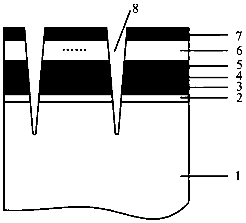
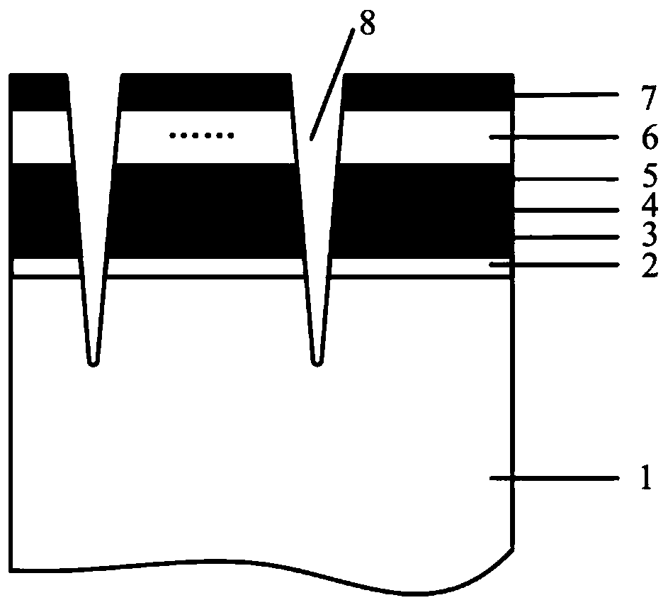
[0026] Example 1: A micro-textured gradient coating tool, the base material of the tool is high-speed steel, the rake face and the flank face of the tool have micro-texture, and the surface of the micro-texture is deposited with alternating layers of ZrVCN+TiSiNbC hard coating and WBSe soft coating. The coating, from the coating to the surface of the tool base material is a ZrN+Zr transition layer in sequence. The ZrVCN+TiSiNbC alternate laminated hard coating in the micro-texture gradient coating tool contains two layers of ZrVCN and two single layers of TiSiNbC, and the thickness of the single layer of ZrVCN and TiSiNbC is less than or equal to 100nm.

[0027] A method for preparing a micro-texture gradient coating tool, using laser-induced liquid plasma processing technology to process a circular hole-shaped micro-texture in the knife-chip contact area on the rake face of the tool and the knife-work contact area on the flank face of the tool; The Zr+ZrN transition layer, Zr...

example 2

[0042] Example 2: A micro-textured gradient coating tool, the tool base material is cemented carbide, the rake face and the flank face of the tool have micro-texture, and the micro-textured surface is deposited with alternating layers of ZrVCN+TiSiNbC hard coating and WBSe Soft coating, from the coating to the surface of the tool base material is a ZrN+Zr transition layer in turn. The ZrVCN+TiSiNbC alternately laminated hard coating in the micro-texture gradient coating tool contains 20 layers of ZrVCN and 20 layers of TiSiNbC single layers, and the thickness of the single layers of ZrVCN and TiSiNbC is less than or equal to 100nm.

[0043] A method for preparing a micro-texture gradient coating tool, using laser-induced liquid plasma processing technology to process a grid-like micro-texture in the tool-chip contact area on the rake face of the tool and the tool-work contact area on the flank face of the tool; The Zr+ZrN transition layer, ZrVCN+TiSiNbC alternate lamination ha...


PUM

PropertyMeasurementUnit
Diameteraaaaaaaaaa
Depthaaaaaaaaaa

Abstract

The invention discloses a cutting tool with micro textures and gradient coatings as well as a preparation method of the cutting tool. The base material of the cutting tool is high-speed steel, hard alloy or ceramic. Firstly, a laser-induced plasma technology is used to form micro textures of different patterns and sizes on the front and back surfaces of the cutting tool; and a method of multi-arcion plating and medium-frequency magnetron sputtering co-deposition is used to prepare Zr+ZrN transition layers, nano laminated layers consisting of alternating ZrVCN+TiSiNbC hard coatings and a WBSesoft coating on the surfaces of the cutting tool. The cutting tool has the advantages of the micro textures, the hard coatings, the soft coating, the nano layers and the laminated structure, and thushas high hardness and good self-lubricating property. During dry cutting, effective continuous lubricating films can be formed on the surfaces of the cutting tool, and the micro textures on the surfaces can perform the functions of reducing friction and collecting wear debris; and the nano laminated coating layers increase the binding force between the coating layers and reduce the internal stressof the coating layers. The cutting tool can be widely used in dry cutting and the cutting of difficult-to-machine materials.

Description

technical field [0001] The invention belongs to the technical field of mechanical cutting tool manufacturing, and relates to a micro-texture gradient coating tool and a preparation method thereof. Background technique [0002] As a new economical and environmentally friendly manufacturing technology, dry cutting has become a hotspot in the research of green manufacturing technology. However, due to the lack of cutting fluid in dry cutting, severe friction occurs between the tool and the workpiece, resulting in severe tool wear and reduced service life. Coating the tool is one of the important ways to improve the performance of the tool. In order to further improve the performance of the tool, the coating tool has been developed from a single layer to a multi-layer and composite; at the same time, the combination of soft coating and hard coating is applied to the Cutting tool, so that the surface of the tool has both high hardness and good self-lubricating effect, thereby si...

Claims


Application Information

Patent Timeline
IPC IPC(8): C23C14/02C23C14/06C23C14/16C23C14/35
CPCC23C14/0036C23C14/022C23C14/0635C23C14/0641C23C14/0664C23C14/165C23C14/352
Inventor 邢佑强刘磊吴泽黄鹏孙东科杨俊杰
Owner SOUTHEAST UNIV
Learn More