
Method for preparing ultra-thin metal grid flexible transparent electrode by ink-jet printing combining electroless plating process

An ultra-thin metal and inkjet printing technology, which is applied in the direction of copying/marking method, printing post-processing, metal material coating process, etc., can solve the problem of increasing the complexity of the electrode material processing process and the high annealing temperature of the metal mesh transparent electrode , metal grid transparent electrode thickness and other issues, to achieve excellent transparent conductivity and uniform morphology, low cost, good oxidation resistance

Inactive Publication Date: 2019-07-05
NANCHANG UNIV
View PDF6 Cites 3 Cited by
  • Summary
  • Abstract
  • Description
  • Claims
  • Application Information

AI Technical Summary

Problems solved by technology

The metal grid transparent electrode prepared by photolithography, electrospinning and patterning technology is very thick and has node resistance. In order to realize its application in optoelectronic devices, it is necessary to increase transfer printing, semi-embedding and other processes or preparation. Composite transparent electrode to overcome, significantly increasing the complexity of the electrode material processing technology
Inkjet printing technology can overcome the large node resistance between the grids and maintain the uniformity of the electrode surface resistance, but the degree of control of the thickness difference between the grid and the substrate material is limited
In addition, the direct use of inkjet printing to prepare metal grid transparent electrodes generally requires a high annealing temperature, which is also contrary to the original intention of green printing.

Method used


Image

  • Method for preparing ultra-thin metal grid flexible transparent electrode by ink-jet printing combining electroless plating process
  • Method for preparing ultra-thin metal grid flexible transparent electrode by ink-jet printing combining electroless plating process
  • Method for preparing ultra-thin metal grid flexible transparent electrode by ink-jet printing combining electroless plating process

Examples


Embodiment 1

[0036]

[0037] a) Weigh 0.09g of tris(hydroxymethyl)methylamine hydrochloride and 0.17g of tris(hydroxymethyl)aminomethane and dissolve in 200mL of deionized water, add 0.4g of dopamine (DA) to dissolve and form a polydopamine (PDA) solution;

[0038] b) Immediately immerse the oxygen plasma-treated substrate (polyethylene terephthalate, PET) in the buffer solution a) and react for 20 minutes, and place the substrate containing the PDA coating in an oven at 60° C. for 15 minutes;

[0039] c) Weigh 2.5015g of polystyrene (PS), stir and dissolve it in 15mL of N,N-dimethylformamide in an oil bath at 60°C, and prepare 15wt% PS ink;

[0040] d) Put PS ink into an inkjet printer, and design a matrix pattern with a line width of 300 μm and a line spacing of 2 mm in the printer programming software, and then perform inkjet printing on a substrate with a PDA coating, and obtain a matrix mask after the ink dries quickly. template pattern;

[0041] e) Add 0.815g of silver nitrate to...

Embodiment 2

[0046]

[0047] a) Weigh 0.09g of tris(hydroxymethyl)methylamine hydrochloride and 0.17g of tris(hydroxymethyl)aminomethane and dissolve in 200mL of deionized water, add 0.4g of dopamine (DA) to dissolve and form a polydopamine (PDA) solution;

[0048] b) Immediately immerse the oxygen plasma-treated substrate (polyethylene terephthalate, PET) in the buffer solution a) and react for 20 minutes, and place the substrate containing the PDA coating in an oven at 60° C. for 15 minutes;

[0049] c) Weigh 0.0427g of polymethylmethacrylate (PMMA), stir and dissolve it in 15mL of N,N-dimethylformamide under the condition of 60°C oil bath, and configure it into 0.3wt% PMMA ink;

[0050] d) PMMA ink is loaded into an inkjet printer, and a matrix pattern of 300 μm line width and 2mm line spacing is designed in the printer programming software, and then inkjet printing is carried out on a substrate with a PDA coating, and the matrix mask is obtained after the ink dries quickly. template...

Embodiment 3

[0056]

[0057] a) Weigh 0.09g of tris(hydroxymethyl)methylamine hydrochloride and 0.17g of tris(hydroxymethyl)aminomethane and dissolve in 200mL of deionized water, add 0.4g of dopamine (DA) to dissolve and form a polydopamine (PDA) solution;

[0058] b) Immediately immerse the oxygen plasma-treated substrate (polyethylene terephthalate, PET) in the buffer solution a) and react for 20 minutes, and place the substrate containing the PDA coating in an oven at 60° C. for 15 minutes;

[0059] c) Weigh 0.0712g of polyacrylonitrile (PAN), stir and dissolve it in 15mL of N,N-dimethylformamide in an oil bath at 60°C, and configure it as 0.5wt% PAN ink;

[0060] d) Put PS ink into an inkjet printer, and design a matrix pattern with a line width of 300 μm and a line spacing of 2 mm in the printer programming software, and then perform inkjet printing on a substrate with a PDA coating, and obtain a matrix mask after the ink dries quickly. template pattern;

[0061] e) Add 0.815g of ...


PUM

PropertyMeasurementUnit
thicknessaaaaaaaaaa

Abstract

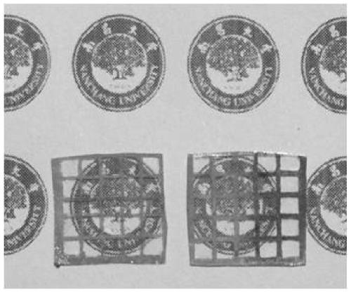
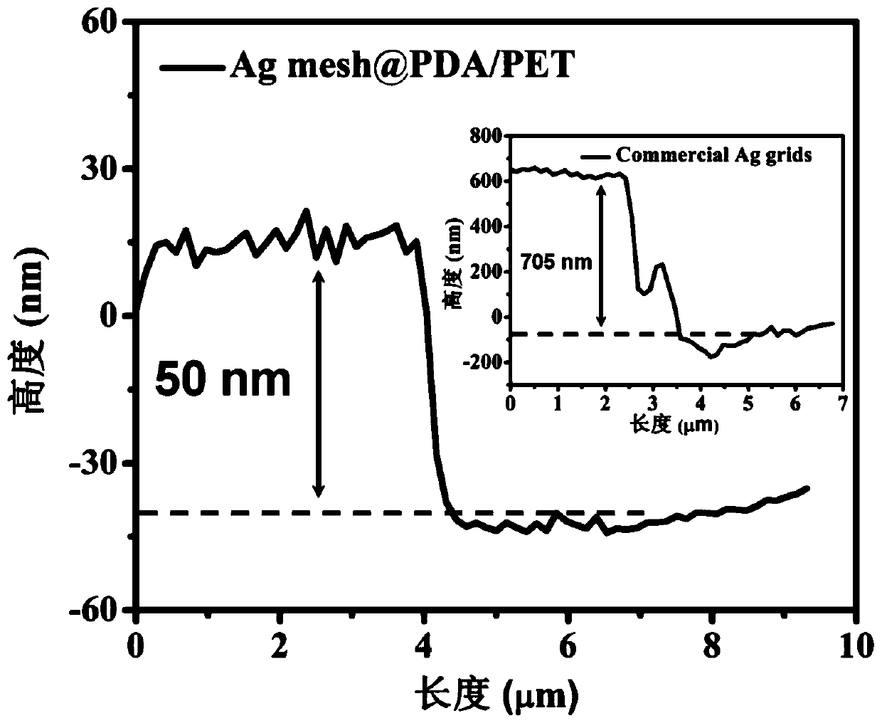
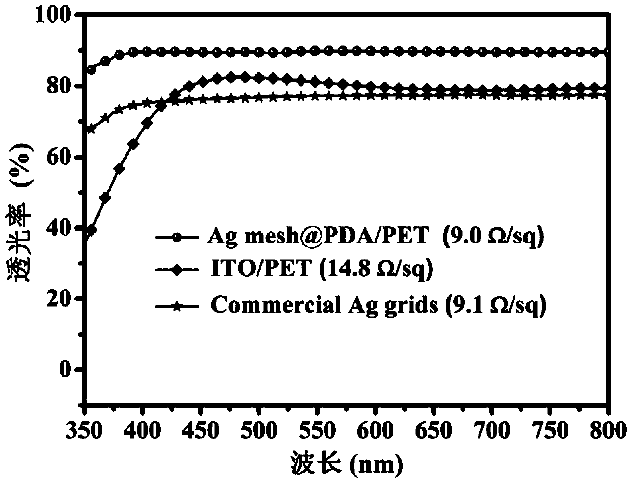
The invention provides a method for preparing an ultra-thin metal grid flexible transparent electrode by ink-jet printing combining electroless plating process. The method comprises the following steps that a water-resistant polymer matrix template is printed in an ink jetting mode on a flexible substrate of an adhesive coating, electroless plating is performed on the exposed adhesive coating pattern, metal particles are selectively deposited to form super-adhesive ultra-thin (50nm) metal grids. The preparation process is a green reaction, and is simple, free of transfer printing, energy-saving, environment-friendly and low in cost; and the square resistance of the prepared metal transparent electrode is 9 ohm / sq, the visible light transmittance reaches 89%, the height difference of the metal grids is uniform in distribution, and the thickness of the metal grids is only 50nm. The electrical conductivity of the ultra-thin metal grids is not obviously changed through exposure of 552h ina high-humidity air environment and adhesion tests of 200 times, so that the method has operation reliability and stability, and is expected to realize large-area industrial production.

Description

technical field [0001] The invention relates to a method for preparing an ultra-thin metal grid flexible transparent electrode by combining inkjet printing with an electroless plating process. Background technique [0002] Due to the excellent characteristics of high light transmittance and high conductivity, metal grid transparent electrodes have broad application prospects and practical potential in the development of commercial flexible transparent electrodes, but there are still many problems before real commercialization. There are extremely important issues that need to be resolved. One of the most important problems is to solve the large thickness difference between the metal grid and the substrate material, weak adhesion, uneven surface resistance distribution and high temperature processing conditions. The metal grid transparent electrode prepared by photolithography, electrospinning and patterning technology is very thick and has node resistance. In order to reali...

Claims


Application Information

Patent Timeline
Patent Type & Authority Applications(China)
IPC IPC(8): C23C18/44C23C18/40B41M5/00B41M7/00
CPCB41M5/0023B41M5/0047B41M5/0064B41M7/00C23C18/1605C23C18/405C23C18/44
Inventor 谈利承陈义旺王青霞孟祥川胡婷
Owner NANCHANG UNIV
Learn More