Lithographic projection apparatus, device manufacturing method, and device manufactured thereby
a technology of lithographic projection and manufacturing method, which is applied in the direction of printers, particle charging/ionising stations, geological measurements, etc., can solve the problems of difficult removal or repair, easy damage to the window itself, and build-up of absorbing layers on the surface of optical elements
- Summary
- Abstract
- Description
- Claims
- Application Information
AI Technical Summary
Benefits of technology
Problems solved by technology
Method used
Image
Examples
embodiment 1
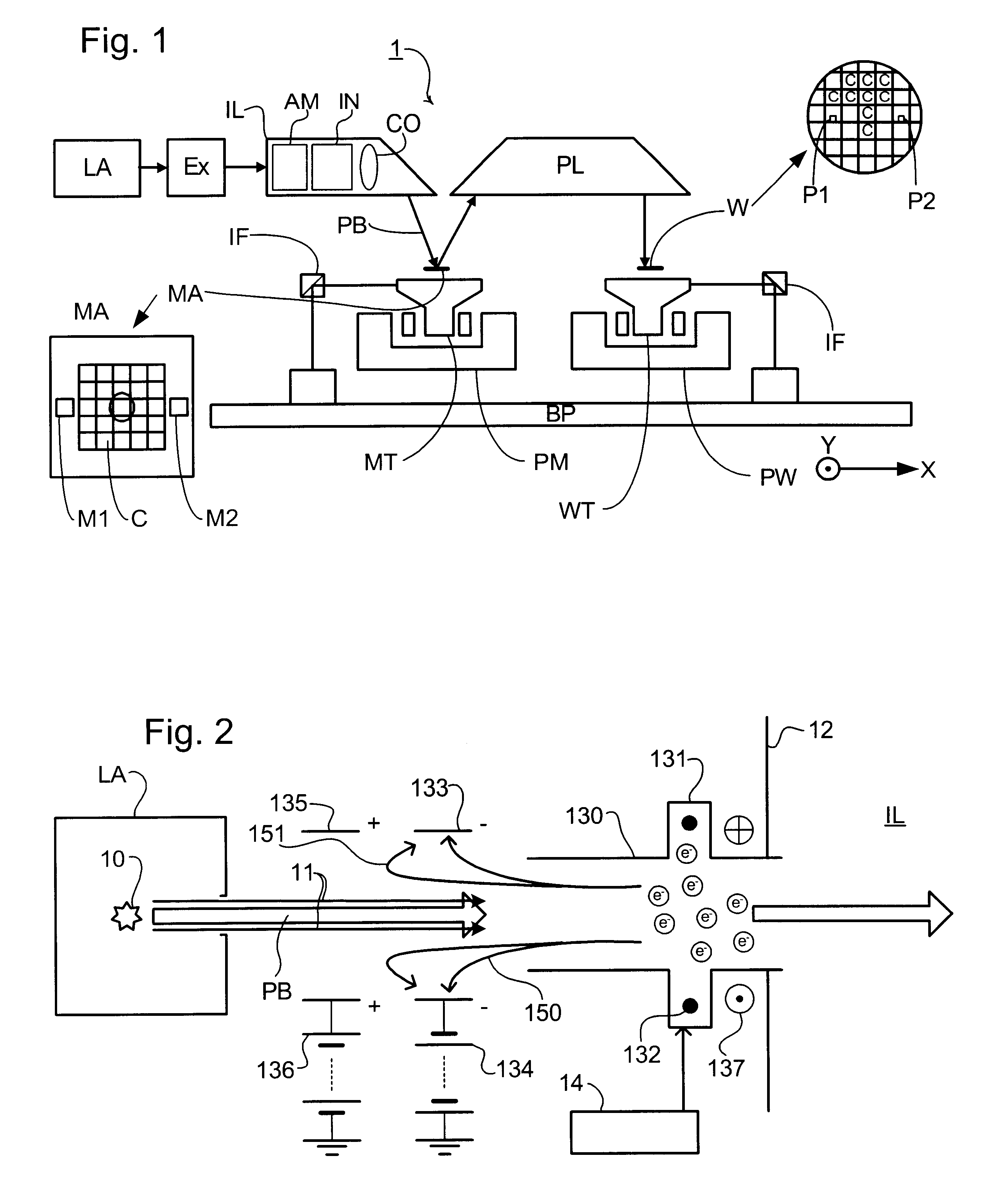
FIG. 1 schematically depicts a lithographic projection apparatus according to a particular embodiment of the invention. The apparatus comprises:
a radiation system LA, IL, for supplying a projection beam PB of radiation (e.g. EUV radiation), which in this particular case also comprises a radiation source LA;
a first object table (mask table) MT provided with a mask holder for holding a mask MA (e.g. a reticle), and connected to first positioning means PM for accurately positioning the mask with respect to item PL;
a second object table (substrate table) WT provided with a substrate holder for holding a substrate W (e.g. a resist-coated silicon wafer), and connected to second positioning means PW for accurately positioning the substrate with respect to item PL;
a projection system ("lens") PL (e.g. refractive, catadioptric or reflective system) for imaging an irradiated portion of the mask MA onto a target portion C (e.g. comprising one or more dies) of the substrate W.
As here depicted, ...
embodiment 2
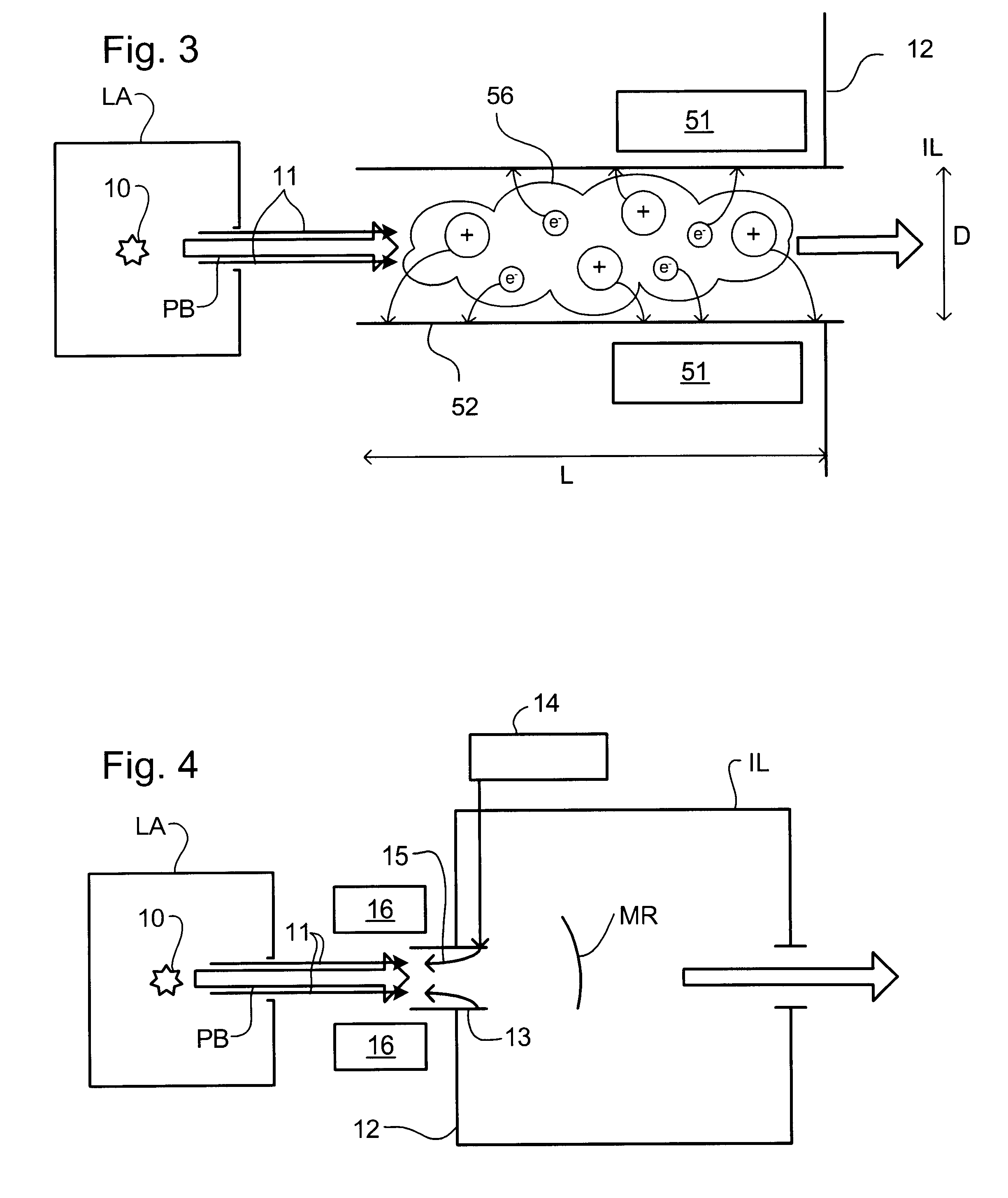
A second embodiment of the invention is similar to the first embodiment save in that the gas is ionized by generating a plasma and ambipolar diffusion used to remove contaminants. FIG. 3 shows the arrangement for generating the plasma, which replaces the ionization means shown in FIG. 2.
A plasma 56 of, in this embodiment, noble gases is generated by a plasma generating means 51 which uses, for example, capacitively or inductively coupled RF discharges, or an a / c discharge, for instance, in the frequency range 10 kHz-20 MHz. The electron energy in the plasma 56 should preferably be 10-20 eV or there should be a great concentration of electrons in a high level metastable state. Although other gases can be used in the plasma 56, noble gases are advisable and in particular He and Ar provide for effective ionization.
As depicted in FIG. 3 the plasma 56 is in a tube 52 having a greater length L than width D. Due to their high temperature the electrons diffuse rapidly and are trapped by the...
embodiment 3
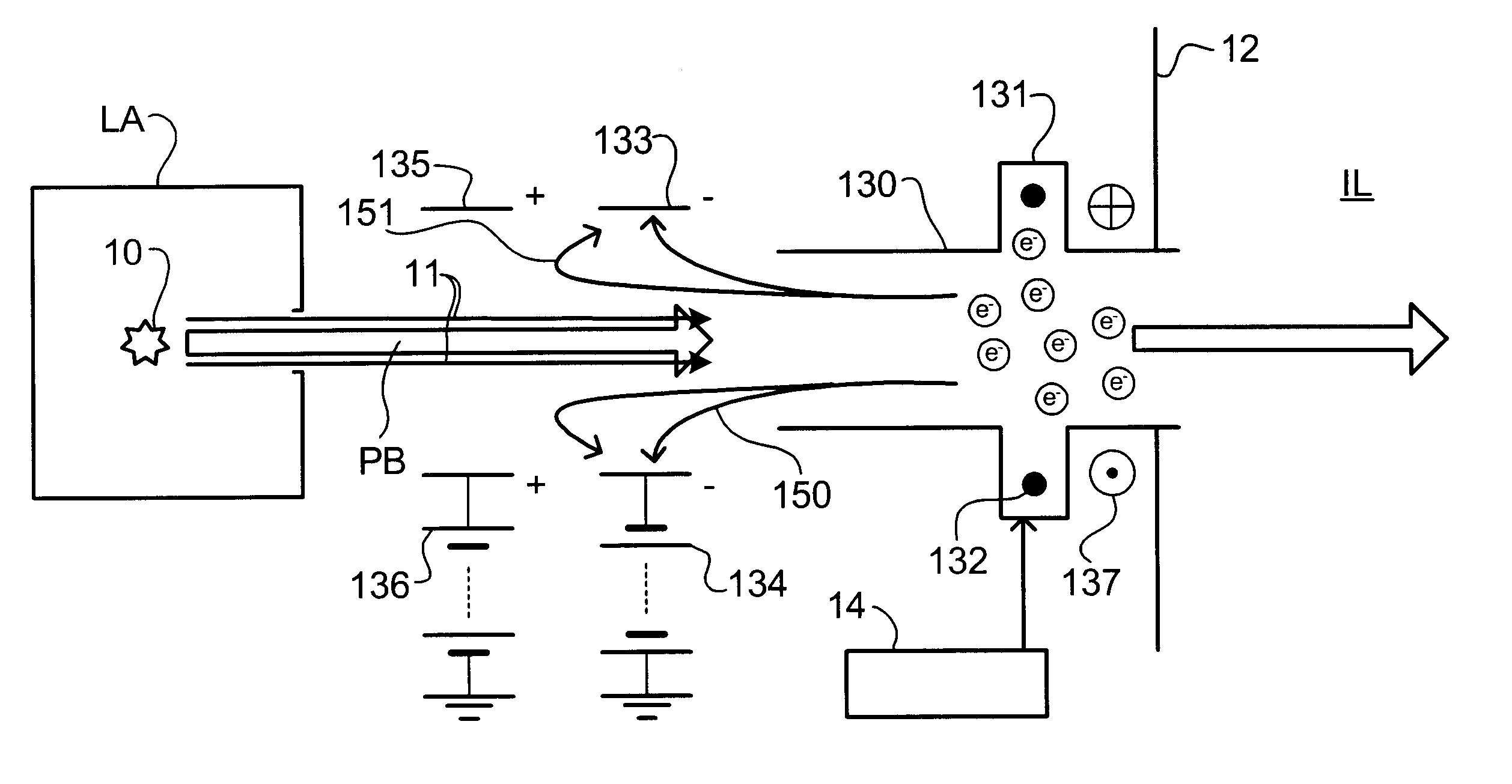
In a third embodiment of the present invention, which may the same as the first or second embodiments of the invention save as described below, a flow of purge gas is provided to impede the contaminant flow towards the illumination system.
A purge gas supply 14 supplies clean, dry purge gas to outlets (not shown) in the interior wall of the tube 13 to establish a flow 15 of purge gas down the tube toward the radiation source LA. The purge gas may be, for example, a pure inert or noble gas or a mixture of such gases that has a minimum absorption coefficient to the radiation of the projection beam.
The purge gas flow 15 intercepts and sweeps up the particles of contaminant particle beam 11 and carries them away from the illumination system IL. Exhaust systems 16 are provided either side of the projection beam PB between the radiation source LA and illumination system IL to remove the purge gas flow and entrained contaminant particles. Vacuum pumps in the exhaust systems 16 extract the p...
PUM
| Property | Measurement | Unit |
|---|---|---|
| wavelength | aaaaa | aaaaa |
| wavelength | aaaaa | aaaaa |
| wavelength | aaaaa | aaaaa |
Abstract
Description
Claims
Application Information
 - R&D
- Intellectual Property
- Life Sciences
- Materials
- Tech Scout
- Unparalleled Data Quality
- Higher Quality Content
- 60% Fewer Hallucinations
Browse by: Latest US Patents, China's latest patents, Technical Efficacy Thesaurus, Application Domain, Technology Topic, Popular Technical Reports.
© 2025 PatSnap. All rights reserved.Legal|Privacy policy|Modern Slavery Act Transparency Statement|Sitemap|About US| Contact US: help@patsnap.com


