
Cadmium telluride thin film solar cell module and preparation method thereof

A solar cell, cadmium telluride technology, applied in electrical components, circuits, photovoltaic power generation, etc., can solve the problems of complex preparation of composite layers, difficult to control, etc., and achieve the effects of efficiency attenuation, prolonging service life, and optimizing contact

Active Publication Date: 2019-05-31
CNBM CHENGDU OPTOELECTRONICS MATERIAL
View PDF6 Cites 3 Cited by
  • Summary
  • Abstract
  • Description
  • Claims
  • Application Information

AI Technical Summary

Problems solved by technology

However, the preparation of the composite layer is complicated and difficult to control

Method used


Image

  • Cadmium telluride thin film solar cell module and preparation method thereof
  • Cadmium telluride thin film solar cell module and preparation method thereof
  • Cadmium telluride thin film solar cell module and preparation method thereof

Examples


preparation example Construction

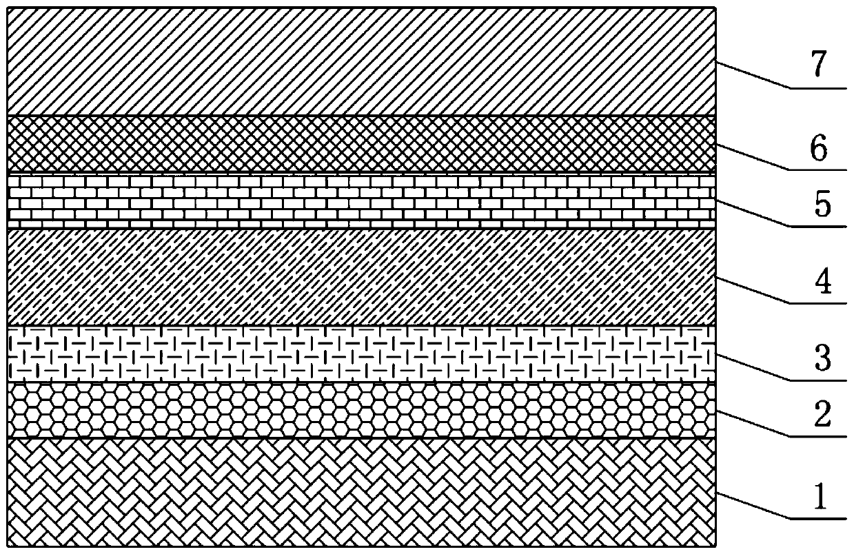
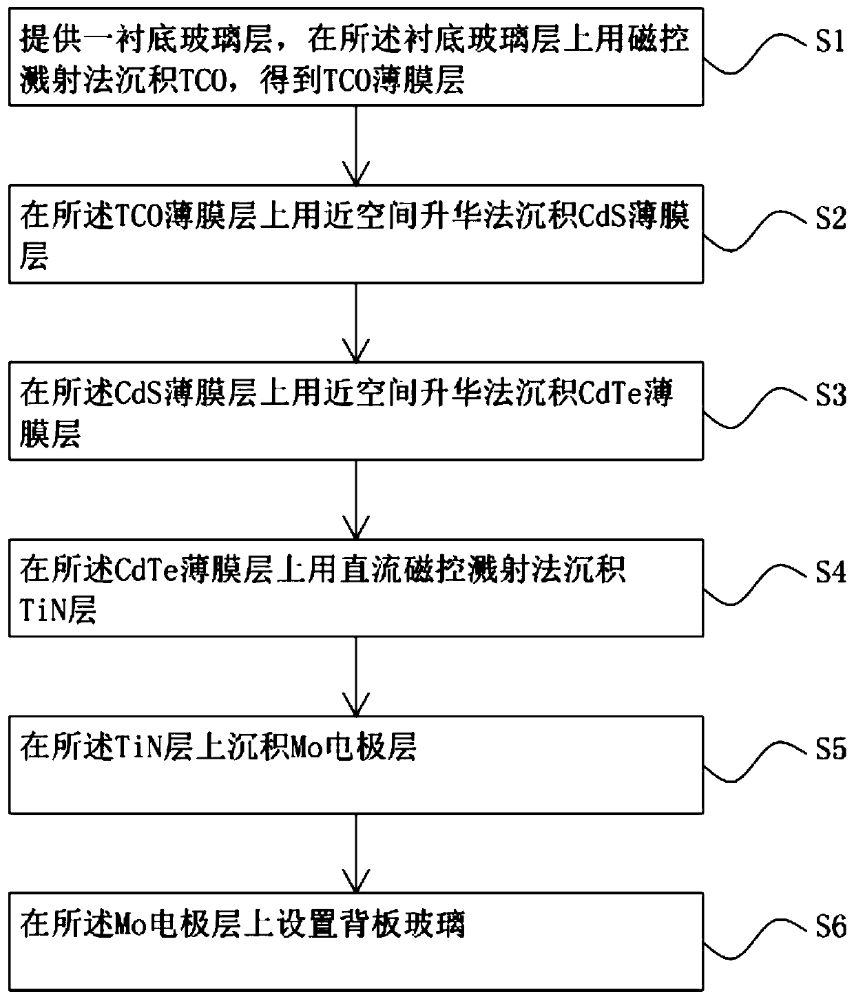
[0034] A method for preparing a cadmium telluride thin film solar cell assembly, comprising the steps of:

[0035] S1 provides a substrate glass layer 1 on which TCO is deposited by magnetron sputtering to obtain a TCO thin film layer 2;

[0036] S2 depositing a CdS thin film layer 3 on the TCO thin film layer 2 by a close-space sublimation method;

[0037] S3 depositing a CdTe thin film layer 4 on the CdS thin film layer 3 by a close space sublimation method;

[0038] S4 deposits a TiN layer on the CdTe film layer 4 by DC magnetron sputtering;

[0039] S5 deposits a Mo electrode layer 6 on the TiN layer;

[0040] S6 disposing a backplane glass layer 7 on the Mo electrode layer 6 .

[0041] Preferably, in the step S4, the TiN layer is coated with a 150 mm circular titanium target in a mixed atmosphere of argon gas with a purity of 99.99% and a nitrogen gas with a purity of 99.95%.

[0042] More preferably, the total pressure of the mixed gas of argon and nitrogen is 0.8pa,...

Embodiment 1

[0045] A substrate glass layer 1 is provided, and TCO is deposited by magnetron sputtering on the substrate glass layer 1 to obtain a TCO film layer 2 with a thickness of 300 nm; CdS, to obtain a CdS film layer 3 with a thickness of 50nm; on the CdS film layer 3, deposit CdTe with a close-space sublimation method to obtain a CdTe film layer 4 with a thickness of 2um; TiN is deposited by sputtering to obtain a TiN layer with a thickness of 50 nm; a Mo electrode layer 6 is deposited on the TiN layer; and a back glass layer 7 is arranged on the Mo electrode layer 6 .

Embodiment 2

[0047] A substrate glass layer 1 is provided, and TCO is deposited by magnetron sputtering on the substrate glass layer 1 to obtain a TCO film layer 2 with a thickness of 400 nm; CdS, to obtain a CdS film layer 3 with a thickness of 120nm; on the CdS film layer 3, deposit CdTe with a close-space sublimation method to obtain a CdTe film layer 4 with a thickness of 4um; TiN is deposited by sputtering to obtain a TiN layer with a thickness of 150 nm; a Mo electrode layer 6 is deposited on the TiN layer; and a backplane glass layer 7 is arranged on the Mo electrode layer 6 .


PUM

PropertyMeasurementUnit
thicknessaaaaaaaaaa
thicknessaaaaaaaaaa
thicknessaaaaaaaaaa

Abstract

The invention discloses a cadmium telluride thin film solar cell module and a preparation method thereof. The cadmium telluride thin film solar cell module comprises a substrate glass layer, a TCO thin film layer, a CdS thin film layer, a CdTe thin film layer, a diffusion barrier layer, a Mo electrode layer, and a backplane glass layer which are arranged in order from bottom to top. The diffusionbarrier layer is a TiN layer. A TiN thin film is used as a back electrode buffer layer instead of Cu. Since the work function of the TiN is 4.7eV and the work function can be deepened by adjusting theratio of Ti to N, the Schottky barrier of the metal back electrode and the cadmium telluride thin film can be reduced, and the contact between the metal back electrode and the cadmium telluride thinfilm can be optimized. In addition, the TiN layer has good stability and has a stopping effect on Na diffusion in the glass, so that the diffusion of the alkali metal Na in the cadmium telluride thinfilm cell is controllable, and is different from the diffusion of doped copper which may diffuse to an interface between the cadmium telluride and the cadmium sulfide in a late stage, destroys a p-n junction characteristics, and greatly reduces efficiency, thereby prolonging a service life.

Description

technical field [0001] The invention relates to the field of thin-film solar cells, in particular to a cadmium telluride thin-film solar cell component and a preparation method thereof. Background technique [0002] Polycrystalline cadmium telluride has attracted extensive attention from industry and science because of its band gap of 1.48eV and high absorption rate. At present, the backplane of commercial cadmium telluride thin film solar cells uses glass, and the alkali metal in the glass will pass through The metal electrode diffuses into the absorber layer and varies with batch-to-batch glass quality fluctuations or changes in cadmium telluride deposition parameters, which are not controlled by actual production. Metal copper is used to improve the tunnel contact barrier between the CdTe absorber layer and the back electrode. Although copper plays an important role in high-performance CdTe solar cells, it is rapidly Diffusion, which degrades the efficiency of CdTe solar...

Claims


Application Information

Patent Timeline
Patent Type & Authority Applications(China)
IPC IPC(8): H01L31/073H01L31/0445H01L31/0216H01L31/18C23C14/35C23C14/06
CPCY02E10/543Y02P70/50
Inventor 彭寿马立云潘锦功傅干华邬小凤
Owner CNBM CHENGDU OPTOELECTRONICS MATERIAL
Learn More