A microwave signal frequency measurement device and method based on cyclic frequency shifting

A microwave signal and frequency measurement technology, applied in the field of optoelectronics, can solve problems such as narrow measurement range, measurement blind area, and low resolution, and achieve the effect of increasing the frequency measurement range and eliminating measurement blind areas

Active Publication Date: 2021-05-25
UNIV OF ELECTRONICS SCI & TECH OF CHINA
View PDF9 Cites 0 Cited by
  • Summary
  • Abstract
  • Description
  • Claims
  • Application Information

AI Technical Summary

Problems solved by technology

Among them, the traditional measurement method is limited by electronic devices, and has the disadvantages of narrow measurement range and susceptibility to electromagnetic interference; while the frequency-power mapping method in the existing microwave photon measurement method cannot measure multiple frequencies, frequency-time mapping method and frequency-space mapping method The resolution of the method is low, and the optical frequency comb down-conversion method has the defects of measurement blind area and low stability

Method used


Image

  • A microwave signal frequency measurement device and method based on cyclic frequency shifting
  • A microwave signal frequency measurement device and method based on cyclic frequency shifting
  • A microwave signal frequency measurement device and method based on cyclic frequency shifting

Examples


Embodiment 1

[0021] The invention provides a microwave signal frequency measurement device based on cyclic frequency shifting, which comprises a laser source, an electro-optical modulator, a signal source to be tested, a cyclic frequency shifting module, a photoelectric detector, a spectrum analysis module, and a control and data processing module, wherein The circular frequency shifting module is composed of a local oscillator signal source, a dual parallel modulator, an acousto-optic frequency shifter, an optical amplifier, an optical bandpass filter, an optical adjustable delay line, a polarization controller and an optical coupler; the local oscillator signal source It is electrically connected to the dual parallel modulator, and the signal source to be tested is electrically connected to the electro-optic modulator; the laser source, the electro-optic modulator, the cyclic frequency shift module, and the photodetector are optically connected in sequence; the light in the cyclic frequenc...

Embodiment 2

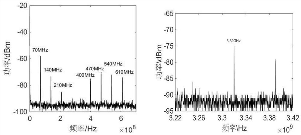
[0041] This embodiment is further optimized on the basis of Embodiment 1, specifically, the laser is in a normal lasing state, the output power is 10mW, and the frequency f 0 = 193THz (wavelength about 1550nm) optical carrier. The intrinsic signal source generates frequency f 1 The sinusoidal signal of = 4GHz is loaded on the dual parallel modulator; the frequency of the acousto-optic frequency shifter is 70MHz; the adjustment of the gain of the erbium-doped fiber amplifier, the optical band-pass filter and the optical adjustable delay line meet the conditions; the output of the microwave signal source to be tested frequency is f 2 = 12.4GHz sinusoidal signal is loaded to the electro-optical phase modulator, the mixed-frequency optical signal is sent to the photodetector for photoelectric detection, the optical signal is converted into an electrical signal, and the spectrum analyzer is used to analyze the 0~f of the electrical signal output by the photodetector. 1 The analys...


PUM


Abstract

The invention discloses a microwave signal frequency measurement device and method based on cyclic frequency shifting, and relates to the field of optoelectronic technology. In order to solve the problem that the existing traditional electronic frequency measurement technology faces the limitation of the frequency measurement range by the electronic bottleneck and the measurement in the microwave photon-assisted frequency measurement technology The problem of low resolution and the inability to realize multi-tone measurement; the present invention is composed of a laser source, an electro-optical modulator, a cyclic frequency shift module, a photoelectric detector, a spectrum analysis module, a control and a data processing module, wherein the cyclic frequency shift module is composed of a local oscillator signal Source, dual parallel modulator, acousto-optic frequency shifter, optical amplifier, optical bandpass filter, optical tunable delay line, polarization controller and optical coupler. In the cyclic frequency shift module, the multi-frequency optical frequency comb is generated by suppressing the single sideband modulation effect of the carrier, and mixed with the signal to be tested in the optical domain, and the microwave signal to be tested is down-converted to an intermediate frequency. By analyzing the spectral components of the intermediate frequency signal, the obtained The frequency of the microwave signal to be measured realizes the frequency measurement of the microwave signal with high resolution, wide frequency range and multi-frequency.

Description

technical field [0001] The invention relates to the field of optoelectronic technology, in particular to a microwave signal frequency measurement device and method based on cyclic frequency shifting. Background technique [0002] With the continuous development of modern radar electronic warfare, instantaneous microwave frequency measurement technology has developed rapidly and has become a very critical technology in electronic warfare. Due to the development of electronic technology, the operating frequency of microwaves continues to rise, and the frequency measurement scheme in the electrical domain cannot meet the development needs of electronic reconnaissance due to the limitation of measurement bandwidth. The frequency measurement system using microwave photonic technology has the characteristics of large instantaneous bandwidth, low loss, anti-electromagnetic interference, etc., and can overcome the bottleneck problem faced by the electronic field in microwave frequen...

Claims


Application Information

Patent Timeline
Patent Type & Authority Patents(China)
IPC IPC(8): G01R23/02
CPCG01R23/02
Inventor 张尚剑杨艺伟邹新海
Owner UNIV OF ELECTRONICS SCI & TECH OF CHINA
Why Eureka
Try Eureka