
Steel pipe grinding device for machining

A technology for mechanical processing and steel pipes, which is applied in the field of steel pipe grinding devices for mechanical processing, can solve the problems of inability to guarantee the uniformity of grinding, poor grinding effect, and low grinding efficiency, and achieve consistent grinding strength, convenient grinding, and uniform grinding Effect

Pending Publication Date: 2019-04-05
HUNAN UNIV OF SCI & ENG
View PDF0 Cites 27 Cited by
  • Summary
  • Abstract
  • Description
  • Claims
  • Application Information

AI Technical Summary

Problems solved by technology

[0003] In the process of steel pipe processing, the outer surface of the steel pipe needs to be polished and derusted. The traditional grinding method is that the worker uses a hand-held grinder to gradually grind the outer circumference of the steel pipe. Since the steel pipe is tubular, the operator needs to constantly adjust the grinding of the grinder. Angle and grinding position, not only consume a lot of physical strength, but also cannot guarantee the uniformity of grinding during the grinding process, resulting in low grinding efficiency and poor grinding effect

Method used


Image

  • Steel pipe grinding device for machining
  • Steel pipe grinding device for machining
  • Steel pipe grinding device for machining

Examples


Embodiment 1

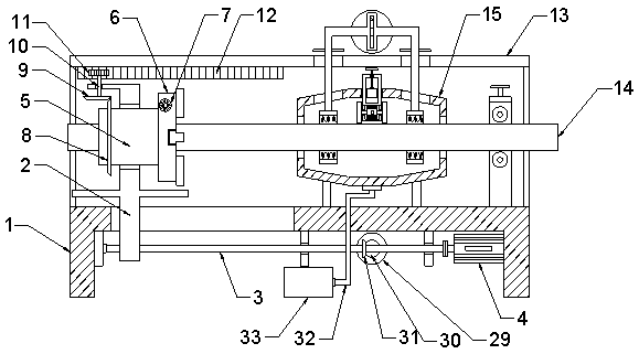
[0022] see Figure 1~3 , in an embodiment of the present invention, a steel pipe grinding device for mechanical processing, comprising a base 1, a steel pipe 14, and a derusting cylinder 15 fixedly connected to the base 1; There is a rotating cylinder 5, and a three-jaw chuck 6 is fixedly connected to one side of the rotating cylinder 5. The outer wall of the three-jaw chuck 6 is provided with a manual adjustment handle 7. By rotating the manual adjustment handle 7, the claws move to the inside, and the steel pipe 14 is adjusted. Clamping and fixing, the fixing of steel pipes with different diameters and specifications is realized by being provided with a three-jaw chuck 6, which is convenient for moving the steel pipes.

[0023] The lower end of the mobile frame 2 extends to the bottom of the base 1, and the base 1 is provided with a first sliding groove for the lateral sliding of the mobile frame 2, and the lower part of the mobile frame 2 moves in the first sliding groove; ...

Embodiment 2

[0027]The lower end of the derusting cylinder 15 is connected with a dust suction pipe 32, and the dust suction pipe 32 is connected with an industrial vacuum cleaner 33. The industrial vacuum cleaner 33 is a common industrial dust collection equipment in this field, and will not be described in detail here. The industrial vacuum cleaner 33 is electrically connected to an external power supply , Efficiently collect the iron filings and dust from grinding, avoid the random scattering of iron filings, prevent the iron filings from polluting the working environment and endangering the health of workers.

[0028] Industrial dust collection equipment can be replaced by electrostatic precipitators or electromagnetic precipitators.

Embodiment 3

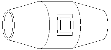
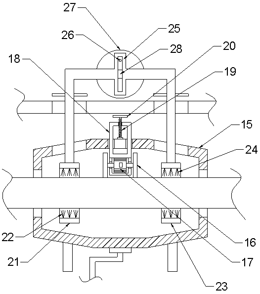
[0030] see image 3 and Figure 4 The difference between this embodiment and Embodiment 2 is that: the grinding wheel 16 is provided with a first derusting cylinder brush 21 near the feeding side of the steel pipe, and the grinding wheel 16 is provided with a second derusting cylinder near the discharging side of the steel pipe 14 Brush 23, the first derusting tube brush 21 is in a cylindrical structure and the inner wall surface is evenly bonded with steel wire bristles 22, the second derusting tube brush 23 is in a cylindrical structure and the inner wall is bonded with soft bristles 24, steel wire bristles 22 Pretreat the surface of the steel pipe 14 so that the iron filings are more likely to peel and warp, which is convenient for subsequent grinding with the grinding wheel 16 to improve the quality and efficiency of grinding; the soft bristles 24 clean the polished steel pipe surface to avoid sticking of the iron filings, or After steel pipe 14 is taken out of derusting ...


PUM


Abstract

The invention discloses a steel pipe grinding device for machining. The steel pipe grinding device comprises a base, a steel pipe and a rust removal barrel fixedly connected with the base. A moving frame is arranged above the base, a rotation barrel is embedded in the moving frame, and one side of the rotation barrel is fixedly connected with a three-jaw chuck. Symmetric grinding abrasive wheels are arranged at the middle position of the rust removal barrel. Through the arrangement of the rotation barrel embedded in the moving frame and rotationally connected with the moving frame, a bevel gear ring, a rolling gear and a rack plate, self-rotation during transverse steel pipe feeding is achieved, and subsequent steel pipe circumference face comprehensive grinding and scrubbing cleaning areconvenient. Through the arrangement of a swinging frame, a first rust removal brush barrel with steel wire bristles and a second rust removal brush barrel with soft bristles, the spindle-shaped rust removal barrel and an industrial dust collector are matched, so that iron scraps are conveniently collected in a centralized manner, and operation environment pollution is avoided.

Description

technical field [0001] The invention relates to the field of machinery, in particular to a steel pipe grinding device for mechanical processing. Background technique [0002] The machine production process refers to the whole process of making products from raw materials (or semi-finished products). For machine production, it includes transportation and storage of raw materials, production preparation, blank manufacturing, processing and heat treatment of parts, product assembly, debugging, painting and packaging, etc. The content of the production process is very extensive. Modern enterprises use the principles and methods of systems engineering to organize and guide production, and regard the production process as a production system with input and output. [0003] In the process of steel pipe processing, the outer surface of the steel pipe needs to be polished and derusted. The traditional grinding method is that the worker uses a hand-held grinder to gradually grind the...

Claims


Application Information

Patent Timeline
Patent Type & Authority Applications(China)
IPC IPC(8): B24B5/04B24B5/35B24B41/06B24B47/12B24B47/22
CPCB24B5/04B24B5/35B24B41/067B24B47/12B24B47/22
Inventor 万李刘志壮唐鑫凌谭开阳李元平
Owner HUNAN UNIV OF SCI & ENG
Learn More