
Gas protection welding wire and manufacturing method thereof

A technology of gas shielded welding wire and manufacturing method, which is applied to manufacturing tools, welding media, welding equipment, etc., can solve the problems of low smoke and dust, and achieve the effects of low smoke and dust, low spatter rate, and improved weld toughness.

Inactive Publication Date: 2019-03-15
BAOSHAN IRON & STEEL CO LTD
View PDF12 Cites 8 Cited by
  • Summary
  • Abstract
  • Description
  • Claims
  • Application Information

AI Technical Summary

Problems solved by technology

The electrode welding process involved in this patent document has good performance, less spatter, and low smoke and dust, but the disclosed technical solution does not involve the design of the welding core composition
[0005] The publication number is CN103008917A, and the publication date is April 3, 2013. The Chinese patent document titled "A New Ultra-Supercritical Ferritic Heat-resistant Steel Welding Rod" discloses a new ultra-supercritical ferritic heat-resistant steel The welding rod adopts H08Cr9WMo welding core and coating in the technical solution disclosed in this patent document, and the coating composition is: 28-40% marble, 18-28% fluorite, 5-10% rutile, 3-8% ferrotitanium , 4-10% silicon powder, 2-5% ferrosilicon, 1-1.8% ferrovanadium, 0.4-0.8% ferroniobium, 1-1.8% nickel powder, 0.4-0.8% soda ash, 0.4-0.8% CMC, 0.2- 0.6% amorphous graphite, 0.6-1.5% ferrochromium nitride, 1.5-3% electrolytic manganese, stable arc, less spatter and good slag removal during welding. However, the technical solution disclosed in this patent document only involves electrode powder Skin composition design, but no welding wire composition design

Method used


Image

  • Gas protection welding wire and manufacturing method thereof
  • Gas protection welding wire and manufacturing method thereof
  • Gas protection welding wire and manufacturing method thereof

Examples


Embodiment 1-6

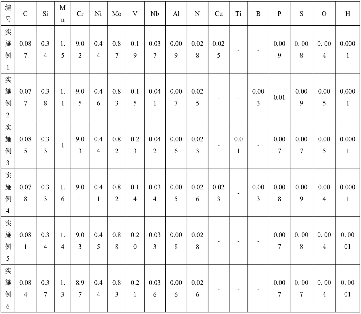
[0057] Table 1 lists the mass percentage of each chemical element in the gas shielded welding wire of Examples 1-6.

[0058] Table 1. (wt%, the balance is Fe and other unavoidable impurity elements except P, S, O, H)

[0059]

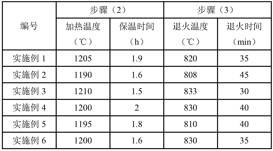
[0060] The manufacturing method of the gas shielded welding wire of embodiment 1-6 includes the following steps:

[0061] (1) Smelting and casting in accordance with the chemical element components listed in Table 1;

[0062] (2) First heat the cast billet in the range of 1190-1210°C for 1.5-2h, and then roll it to obtain a square billet, or heat the cast billet in the range of 1090-1110°C for 30-60min, and then forge it to obtain a square billet. Billet

[0063] (3) Rolling to obtain wire rod;

[0064] (4) Wire rod annealing: annealing temperature is 805-835℃, annealing time is 30-45min;

[0065] (5) Rolling or drawing to obtain gas shielded welding wire.

[0066] It should be noted that in the welding process, the shielding gas is used as the volume percentage of...


PUM

PropertyMeasurementUnit
Tensile strengthaaaaaaaaaa
Impact toughnessaaaaaaaaaa
Tensile strengthaaaaaaaaaa

Abstract

The invention discloses a gas protection welding wire which comprises, by mass, 0.06-0.15% of C, 0.15-0.50% of Si, 0.5-2.0% of Mn, 8.5-10% of Cr, 0.4-0.8% of Ni, 0.8-1.2% of Mo, 0.10-0.30% of V, 0.02-0.08% of Nb, greater than 0 and smaller than or equal to 0.05% of Al, 0.02-0.07% of N, and the balance being iron and other inevitable impurities. In addition, the invention further discloses a manufacturing method of the gas protection welding wire, comprising the steps: (1), smelting and casting; (2), making a square billet; (3) rolling to obtain a wire rod; (4) wire rod annealing, wherein the annealing temperature is 805-835 DEG C; and (5) rolling or drawing to obtain the gas shielded welding wire. The tensile strength of deposited metal obtained by welding by the gas shielded welding wireis greater than or equal to 600 MPa, and the elongation is greater than or equal to 17 percent.

Description

Technical field [0001] The invention relates to a welding wire and a manufacturing method thereof, in particular to a gas shielded welding wire and a manufacturing method thereof. Background technique [0002] With the increasing demand for energy in industry and residents' lives, the working coefficient and thermal efficiency of power station boilers are gradually increasing. Countries all over the world are vigorously developing ultra-supercritical power station boilers, which put forward higher requirements for boiler pressure components. 9Cr-1Mo steel (T / P91 steel for short) is a ferritic heat-resistant stainless steel with excellent high-temperature performance. The performance is between 2.25Cr-1Mo (T22 / P22) low alloy steel and austenitic stainless steel. It can be used as the steam pipe of the supercritical pressure unit of nuclear power plant (the wall temperature can be up to 650℃, and the steam pressure is above 240 atmospheres). This kind of steel pipe has been put in...

Claims


Application Information

Patent Timeline
IPC IPC(8): B23K35/30B23K35/40
CPCB23K35/3086B23K35/40
Inventor 韩纪鹏翟瑞银刘湘江
Owner BAOSHAN IRON & STEEL CO LTD
Learn More