Polarizing plate and optical display including polarizing plate
A polarizer and polarizer technology, applied in the field of polarizers
- Summary
- Abstract
- Description
- Claims
- Application Information
AI Technical Summary
Problems solved by technology
Method used
Image
Examples
preparation example 1
[0132]A black pigment was used as the pigment dispersant (A) containing 30% by weight of the pigment. Specifically, a ratio of silver-tin alloy (TMP-DC-1, Sumitomo Oosaka Cement Co., Ltd.) (solid content: 30%, silver to tin) was compared at the ratio listed in Table 1. A pigment dispersant (A-1) with a weight ratio of 7:3) was tested with a pigment dispersant (A-2) containing carbon black (CI-M-050, Sakata Co., Ltd.). mix. Using aliphatic polyurethane (B-1) (SUO-1000, Shina T&C Co., Ltd.) and acrylic pressure-sensitive adhesive resin (B-2) (WA-9263 , Wooin ChemTech Co., Ltd.) as the binder resin (B). In addition, use melamine curing agent (M60, thermosetting initiator, Wuying Chemical Technology Co., Ltd.) as initiator (D), use propylene glycol methyl ether acetate as solvent (E), and use 765W (Tego Co., Ltd. Co., Ltd.)) as the silane coupling agent (F).
[0133] Prepared by adjusting the amount (unit: weight %) of pigment dispersant (A), binder resin (B), initiator (D), s...
preparation example 2
[0137] A black pigment was used as the pigment dispersant (A) containing 30% by weight of the pigment. Specifically, a pigment containing a silver-tin alloy (TMP-DC-1, Sumitomo Osaka Cement Co., Ltd.) (solid content: 30%, weight ratio of silver to tin = 7:3) was dispersed at the ratios listed in Table 2 The agent (A-1) was mixed with the pigment dispersant (A-2) containing carbon black (CI-M-050, Sakata Co., Ltd.). Aliphatic polyurethane (SUO-1000, Xinna T&C Co., Ltd.) was used as the binder resin (B), and dipentaerythritol hexaacrylate (Hannong Chemical Co. Ltd.) was used as reactive unsaturated compound (C). In addition, photopolymerization initiator IGR 369 was used as the initiator (D), propylene glycol methyl ether acetate was used as the solvent (E), and 765W (Tego Co., Ltd.) was used as the silane coupling agent (F).
[0138] By adjusting the amount of pigment dispersant (A), binder resin (B), reactive unsaturated compound (C), initiator (D), solvent (E) and silane co...
example 1
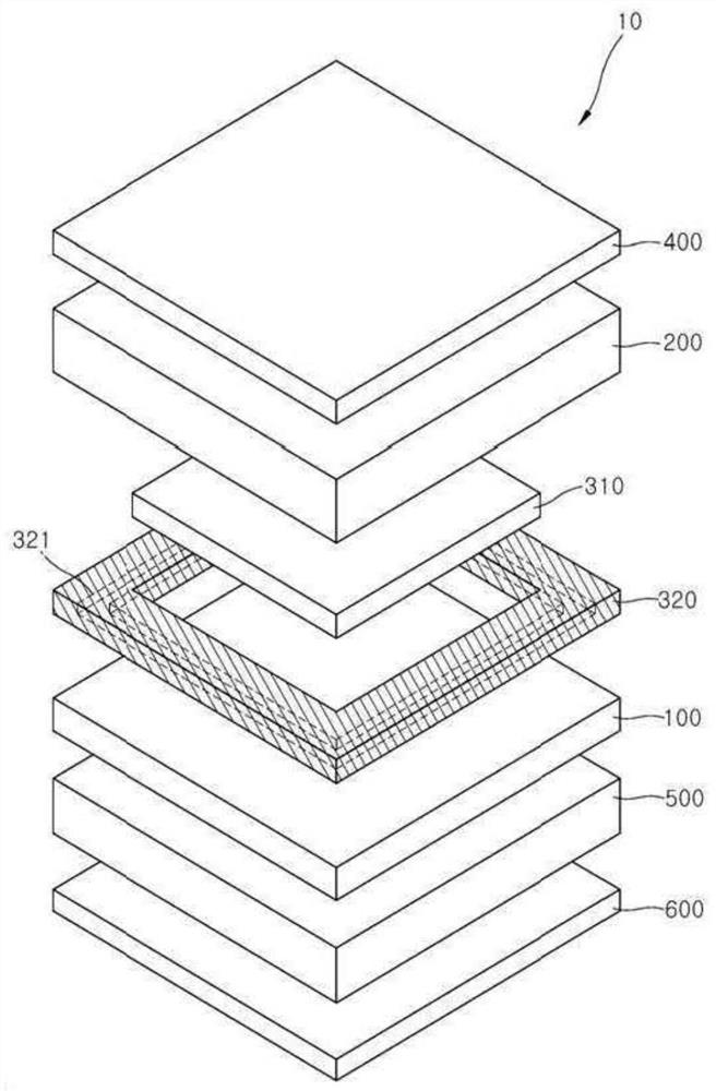
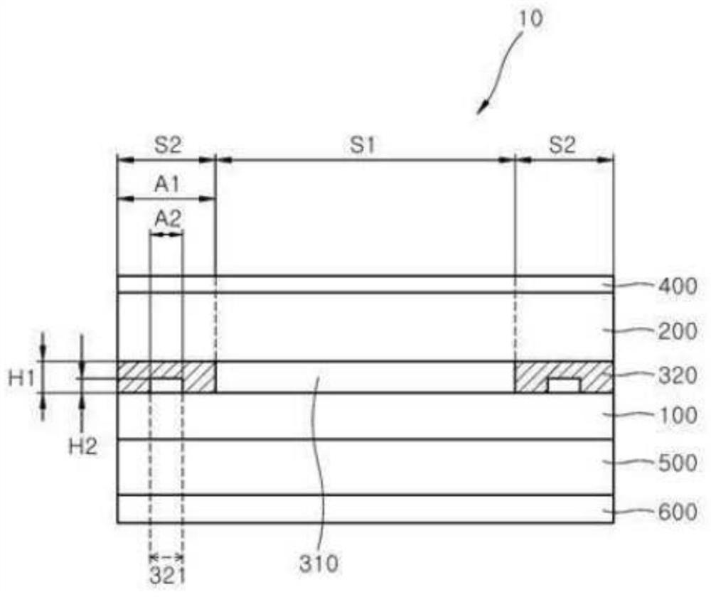
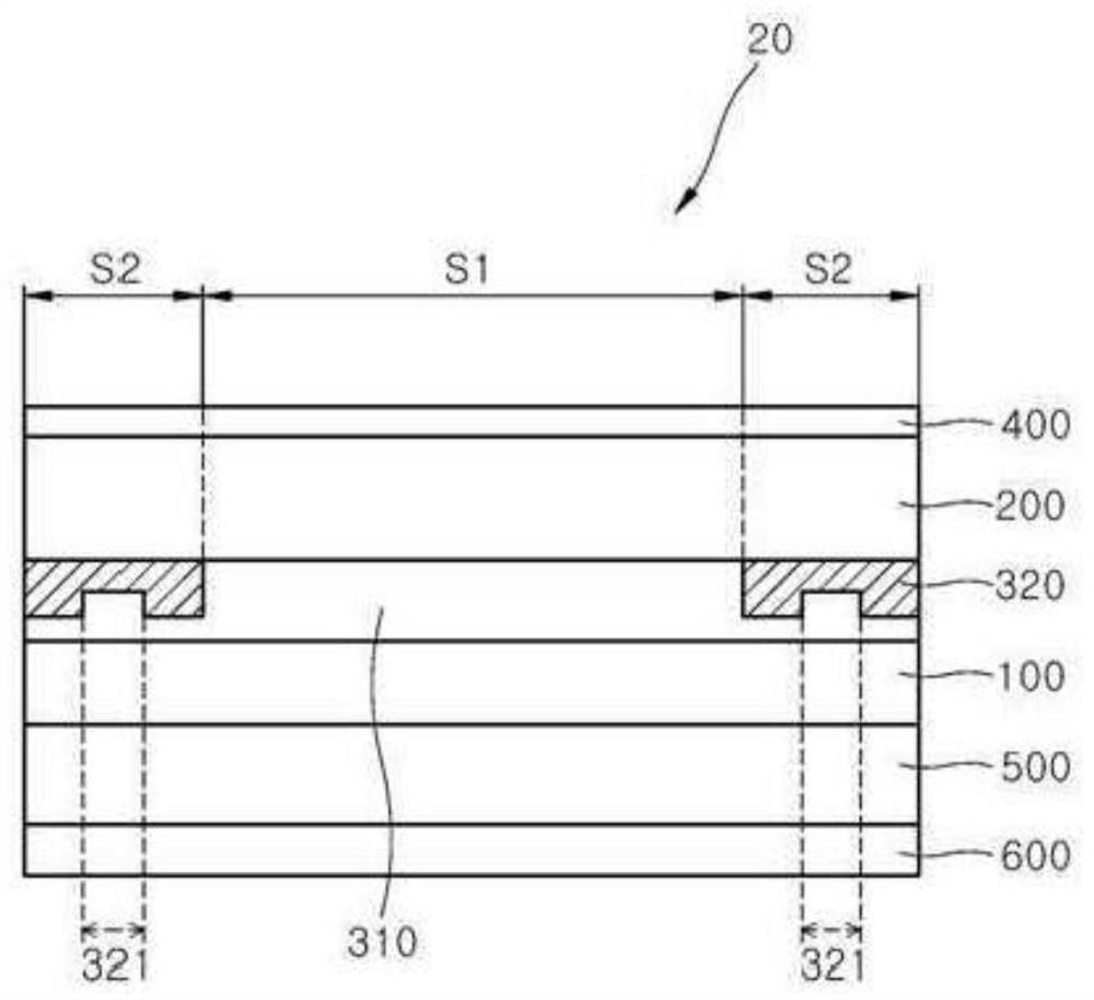
[0142] Along a polyethylene terephthalate (PET) film (haze: 0.3%, DSG-17(Z) PET, DNP limited Company) on the periphery of the lower surface to form a printing pattern: the composition prepared in Preparation Example 1 was gravure-coated along the periphery of its lower surface. The printed pattern was composed of a two-layer structure including a first printed layer and a second printed layer, and was thermally cured at 85° C. for 2 minutes to form a printed layer (thickness: 2.4 μm). Coating of the composition for the printing layer is performed multiple times to form steps, thereby forming image 3 The curved fixing part shown.
[0143] A polyvinyl alcohol film (thickness: 60 μm, degree of polymerization: 2,400, degree of saponification: 99.0%, VF-PS6000, Kuraray Co., Ltd., Japan) was swelled in an aqueous solution at 25° C., and then Dyeing and stretching were performed at 30°C in a dyeing bath containing iodide ions. Next, the dyed polyvinyl alcohol film was further str...
PUM
| Property | Measurement | Unit |
|---|---|---|
| thickness | aaaaa | aaaaa |
| thickness | aaaaa | aaaaa |
| thickness | aaaaa | aaaaa |
Abstract
Description
Claims
Application Information
 - R&D Engineer
- R&D Manager
- IP Professional
- Industry Leading Data Capabilities
- Powerful AI technology
- Patent DNA Extraction
Browse by: Latest US Patents, China's latest patents, Technical Efficacy Thesaurus, Application Domain, Technology Topic, Popular Technical Reports.
© 2024 PatSnap. All rights reserved.Legal|Privacy policy|Modern Slavery Act Transparency Statement|Sitemap|About US| Contact US: help@patsnap.com


