
Method for grinding a bevel gear

A bevel gear, grinding technology, applied in the direction of grinding machine parts, components with teeth, gear tooth manufacturing devices, etc., can solve the problems of reduced machining accuracy, time-consuming, etc. The effect of conversion

Pending Publication Date: 2021-03-16
KLINGELNBERG AG
View PDF5 Cites 0 Cited by
  • Summary
  • Abstract
  • Description
  • Claims
  • Application Information

AI Technical Summary

Problems solved by technology

The changeover is time-consuming and results in reduced machining accuracy compared to machining in the same clamping

Method used


Image

  • Method for grinding a bevel gear
  • Method for grinding a bevel gear
  • Method for grinding a bevel gear

Examples


Embodiment Construction

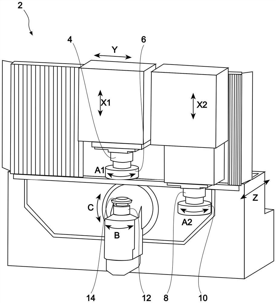
[0058] figure 1 A twin-spindle machine tool 2 is shown, which is a bevel gear grinding machine 2 . The twin-spindle machine tool 2 has a first tool spindle 4 . A first grinding tool 6 is fastened to the first tool spindle 4 . The twin-spindle machine tool 2 has a second tool spindle 8 . A second grinding tool 10 is fastened to the second tool spindle 8 .

[0059] The first tool spindle 4 is designed to drive a first grinding tool 6 in rotation (axis of rotation A1 ). The first tool spindle 4 is movable in translation along the axes X1, Y and Z, respectively.

[0060] The second tool spindle 8 is designed to drive a second grinding tool 10 in rotation (axis of rotation A2 ). The second tool spindle 8 is movable in translation along the axes X2, Y and Z, respectively.

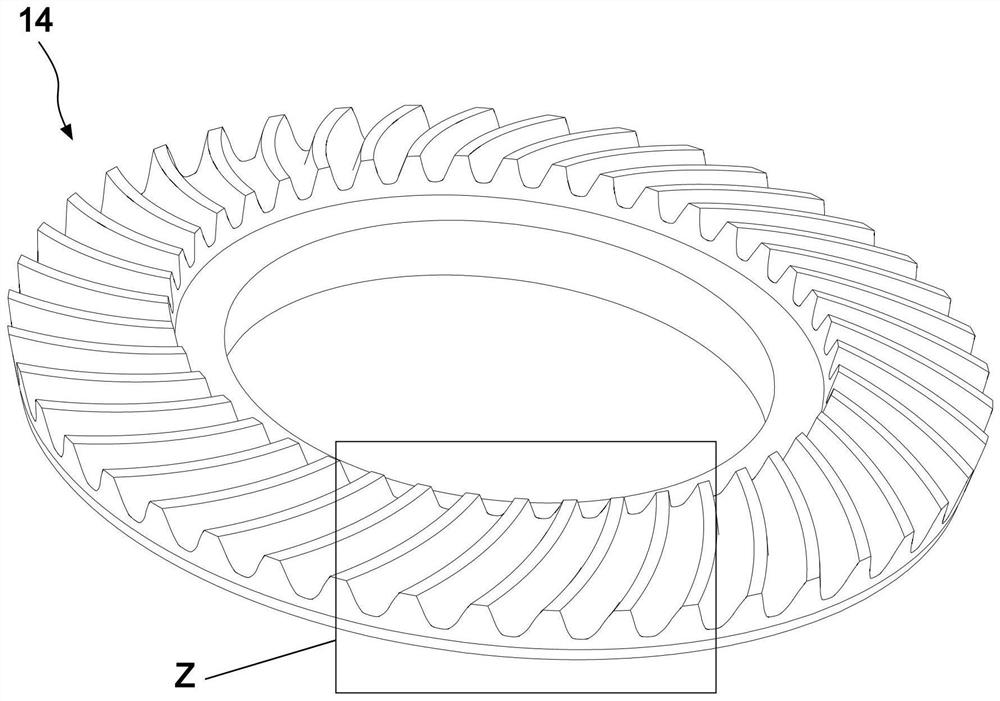
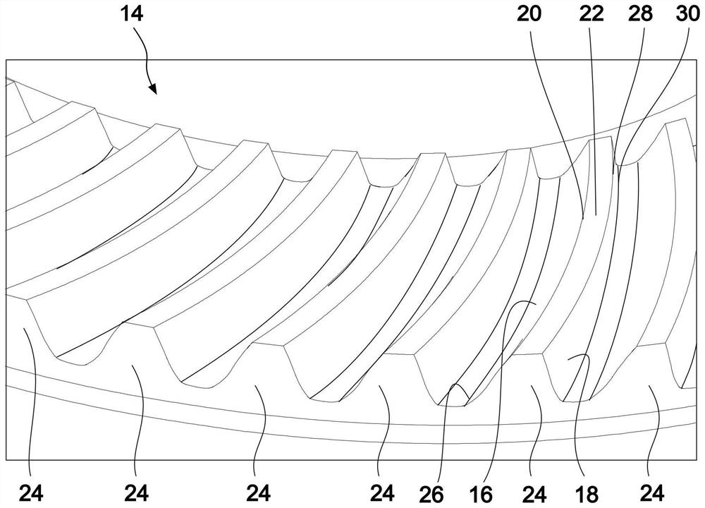
[0061] A pre-toothed and hardened bevel gear 14 or bevel gear workpiece 14 is fastened to the workpiece spindle 12 of the twin-spindle machine tool 2 . The terms bevel gear and bevel gear workpiece are use...


PUM

PropertyMeasurementUnit
surface roughnessaaaaaaaaaa

Abstract

The invention provides a method for grinding a bevel gear, the method comprising the method steps of clamping a bevel gear (14) to be ground on a workpiece spindle (12) of a bevel gear grinding machine (2); first grinding the tooth flanks (16, 18) of the bevel gear (14) with a first grinding tool (6), wherein the first grinding tool (6) is arranged on a first tool spindle (4) of the bevel gear grinding machine (2); finely grinding the tooth flanks (16, 18) of the bevel gear (14) with a second grinding tool (10), wherein the second grinding tool (10) is arranged on a second tool spindle (8) ofthe bevel gear grinding machine (2).

Description

technical field [0001] The invention relates to a method for grinding bevel gears. Background technique [0002] Bevel gear teeth are usually pre-toothed, hardened and finally finished. The fine machining can be achieved, for example, by grinding and / or grinding. [0003] Grinding of bevel gear teeth can be performed in one, two or more processes or cycles, depending on the size of the component and depending on the required machining quality. Here, the grinding tool can be dressed as required. [0004] In this way, for example, bevel gear teeth can be ground on a single machine tool in two cycles in one clamping and with one grinding tool. In order to achieve a particularly high surface quality, it can be provided that the grinding tool is reconditioned before each individual cycle. In this case, the grinding tool is firstly dressed for the primary grinding process in order to optimally dress the grinding tool with respect to its geometry and / or sharpness for the primar...

Claims


Application Information

Patent Timeline
Patent Type & Authority Applications(China)
IPC IPC(8): B23F9/02
CPCB23F9/02B23F23/1225B23F9/025B23F19/12B23F23/1206B24B1/00B24B53/075
Inventor 卡尔-马丁·里贝克罗尔夫·沙勒斯特
Owner KLINGELNBERG AG
Learn More