A kind of microlens array and its preparation method
A micro-lens array and hexagonal technology, applied in the field of micro-lens array, can solve the problems of easy wear, poor process uniformity, low efficiency, etc., and achieve the effects of feasible operation process, good optical performance, and reasonable theoretical basis.
- Summary
- Abstract
- Description
- Claims
- Application Information
AI Technical Summary
Problems solved by technology
Method used
Image
Examples
Embodiment 1
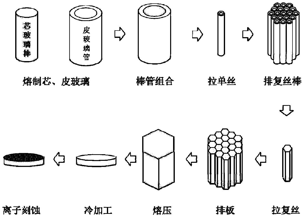
[0032] Such as figure 1 As shown, this embodiment provides a method for manufacturing a microlens array, including the following steps:
[0033] (1) Use silicate glass to prepare cylindrical core material rods (ie, core glass rods below), with an outer diameter of 29mm and a length of 500mm; select borate glass to prepare cylindrical skin tubes (ie, skin glass tubes below) , The outer diameter is 36mm, the wall thickness is 3mm, and the length is 600mm.
[0034] (2) Combine the sheathed glass tube and the core glass rod into a preform, and use a drawing furnace to draw the preform into a cylindrical monofilament with an outer diameter of 0.6mm and a length of 600mm. The temperature of the drawing furnace is 800℃; The monofilaments are closely packed and arranged into hexagonal cylindrical multifilament rods with opposite sides of 30mm and 600mm long. The hexagonal cylindrical multifilament rods are drawn into hexagonal cylindrical multifilaments with opposite sides of 0.5mm through...
Embodiment 2
[0039] Such as figure 1 As shown, this embodiment provides a method for manufacturing a microlens array, including the following steps:
[0040] (1) Choose silicate glass to prepare a square cylindrical core material rod with 29mm opposite sides and 500mm long; choose borate glass to prepare a square cylindrical skin tube with 36mm opposite sides, 3mm wall thickness and 600mm long.
[0041] (2) Combine the skin glass tube and the core glass rod to form a preform, and use a wire drawing furnace to draw the preform into a square cylindrical monofilament with opposite sides 0.6 mm and a length of 600 mm. The temperature of the drawing furnace is 800 ℃; Stacked and arranged into square cylindrical multifilament rods with opposite sides of 30mm and length of 600mm, the multifilament rods are drawn into square cylindrical multifilaments with opposite sides of 0.5mm through a drawing furnace, and the temperature of the drawing furnace is 900℃; Closely packed and arranged into square cylin...
Embodiment 3
[0046] Such as figure 1 As shown, this embodiment provides a method for manufacturing a microlens array, including the following steps:
[0047] (1) Choose silicate glass to prepare a regular hexagonal cylindrical core material rod with 29mm opposite sides and 500mm long; choose borate glass to prepare a regular hexagonal cylindrical skin tube with 36mm opposite sides, 3mm wall thickness and 600mm long.
[0048] (2) Combine the skin glass tube and the core glass rod to form a preform, and use a wire drawing furnace to draw the preform into a hexagonal monofilament with opposite sides of 0.6 mm and a length of 600 mm. The temperature of the drawing furnace is 800 ℃; The hexagonal cylindrical monofilament is closely packed and arranged into a hexagonal cylindrical multifilament rod with the opposite side size of 30mm and a length of 600mm. The hexagonal cylindrical multifilament rod is drawn by a drawing furnace into a regular hexagonal cylindrical complex with opposite sides 0.5mm. ...
PUM
| Property | Measurement | Unit |
|---|---|---|
| pore size | aaaaa | aaaaa |
| thickness | aaaaa | aaaaa |
| diameter | aaaaa | aaaaa |
Abstract
Description
Claims
Application Information
 - R&D
- Intellectual Property
- Life Sciences
- Materials
- Tech Scout
- Unparalleled Data Quality
- Higher Quality Content
- 60% Fewer Hallucinations
Browse by: Latest US Patents, China's latest patents, Technical Efficacy Thesaurus, Application Domain, Technology Topic, Popular Technical Reports.
© 2025 PatSnap. All rights reserved.Legal|Privacy policy|Modern Slavery Act Transparency Statement|Sitemap|About US| Contact US: help@patsnap.com


