
Broadband Signal Phase Stable Transmission System Based on Microwave Photonic Link

A microwave photonic link and broadband signal technology, applied in the field of microwave photonics, can solve the problems of limiting phase control accuracy, poor signal transmission quality, low pilot signal frequency, etc. The effect of high phase stabilization accuracy

Active Publication Date: 2019-12-20
CHINA ELECTRONIC TECH GRP CORP NO 38 RES INST
View PDF5 Cites 0 Cited by
  • Summary
  • Abstract
  • Description
  • Claims
  • Application Information

AI Technical Summary

Problems solved by technology

However, since a low-frequency pilot signal is added to the transmitted signal, it usually has a corresponding pilot signal received together at the receiving end, resulting in poor signal transmission quality in some cases, especially the transmitted signal itself Contains low frequency signal components
Moreover, the phase stability control accuracy of the pilot signal is proportional to the pilot frequency. At the same time, to avoid the pilot signal from interfering with the transmission signal, the frequency of the pilot signal is generally very low, thus limiting the phase control accuracy.

Method used


Image

  • Broadband Signal Phase Stable Transmission System Based on Microwave Photonic Link
  • Broadband Signal Phase Stable Transmission System Based on Microwave Photonic Link
  • Broadband Signal Phase Stable Transmission System Based on Microwave Photonic Link

Examples


Embodiment Construction

[0021] The above and other technical features and advantages of the present invention will be described in more detail below in conjunction with the accompanying drawings.

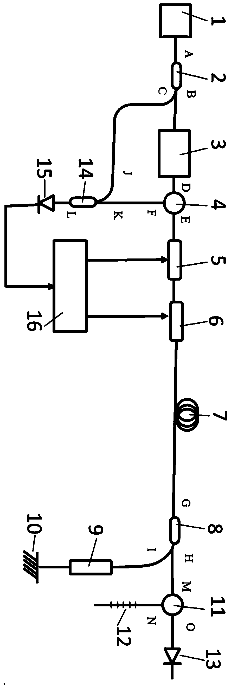
[0022] Such as figure 1 as shown, figure 1 It is a circuit diagram of a broadband radio frequency signal phase-stable transmission system based on a microwave photonic link in the present invention; the broadband radio frequency signal phase-stable transmission system based on a microwave photonic link in the present invention includes a transmitting end, a receiving end and a long optical fiber 7; The transmitting end and the receiving end are connected through the long optical fiber 7 .

[0023] The transmitting end includes a laser module 1, a first fiber coupler 2, a photoelectric modulation module 3, a first fiber circulator module 4, a fast adjustment module 5, a slow adjustment module 6, a third fiber coupler 14, a low-frequency photodetector device 15, signal demodulation processing and feedback ...


PUM


Abstract

The invention discloses a broadband signal stable phase transmission system based on microwave photonic link, which comprises a transmitting end, a receiving end and a long optical fiber. The transmitting end and the receiving end are connected through the long optical fiber; the receiving end comprises a second optical fiber coupler, an acousto-optic frequency shifter module, a Faraday rotating mirror, a second optical fiber loop module, a chirped grating and a high-frequency photodetector. The invention performs frequency shift processing on the optical signal, returns the modulated light byusing a Faraday rotating mirror to avoid interfering with the transmitted signal, demodulates the phase fluctuation in the optical fiber through optical domain interference and carries out feedback control processing, so that the invention has extremely high phase stabilization accuracy and avoids the problem of pilot signal interference. At the same time, the invention adopts the compensation structure of the chirped grating to avoid the problem of out-of-phase control caused by the wavelength drift of the light source.

Description

technical field [0001] The invention relates to the field of microwave photonics for optical fiber transmission of radio frequency signals, in particular to a broadband signal phase-stable transmission system based on microwave photonic links. Background technique [0002] The phase-stable transmission technology of broadband radio frequency signals is widely used in radio astronomy detection, radar radio technology, electronic information countermeasures and other fields. Today's many fields have put forward higher and higher requirements for the bandwidth, phase stability accuracy, spurious suppression and other indicators of transmitted radio frequency signals. However, traditional radio frequency signals are usually transmitted by radio frequency cables, and the system is usually relatively large, and the overall Heavy quality, large signal transmission loss, limited bandwidth, high cost, etc. [0003] Compared with radio frequency cable transmission, optical fiber has ...

Claims


Application Information

Patent Timeline
Patent Type & Authority Patents(China)
IPC IPC(8): H04B10/2507H04B10/556
CPCH04B10/2507H04B10/5561
Inventor 戴泽璟王凯吴彭生余昊
Owner CHINA ELECTRONIC TECH GRP CORP NO 38 RES INST
Learn More