
Multi-band antenna package structure, manufacturing method thereof and communication device

a technology of antenna package structure and antenna, applied in the direction of radiating element structure, basic electric elements, independent non-interfering antenna combinations, etc., can solve the problems of non-contact joints, large space occupation, and unstable manufacturing process of package structure, and achieve high flexibility, high cost efficiency, and high scalability.

Active Publication Date: 2019-06-20
NAT CHUNG SHAN INST SCI & TECH
View PDF1 Cites 30 Cited by
  • Summary
  • Abstract
  • Description
  • Claims
  • Application Information

AI Technical Summary

Benefits of technology

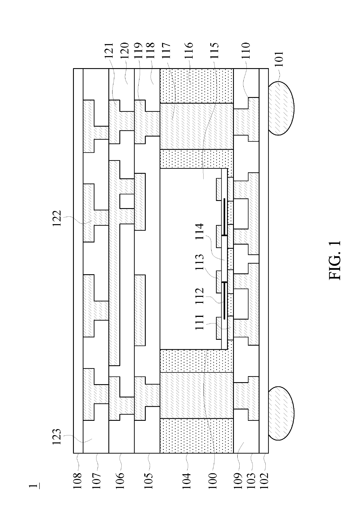
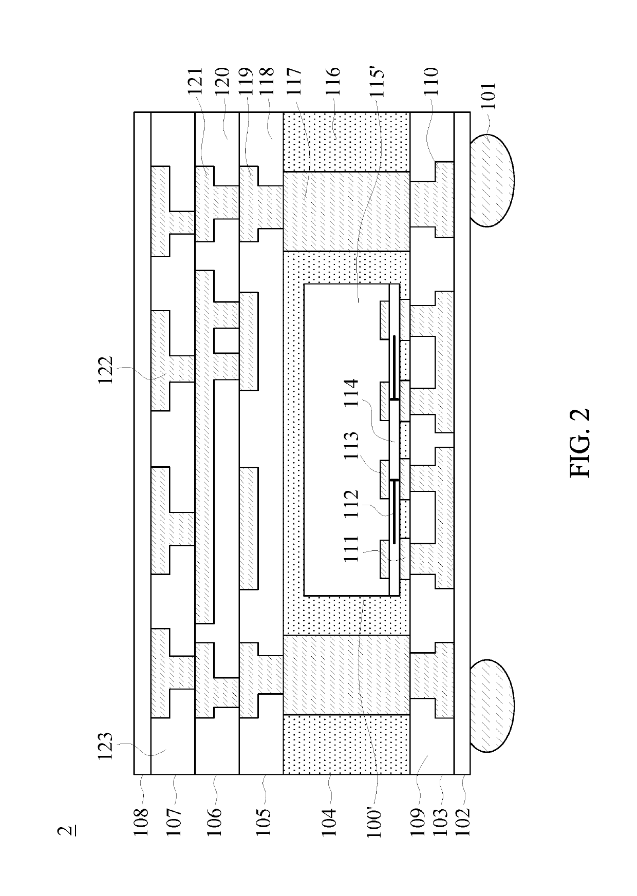
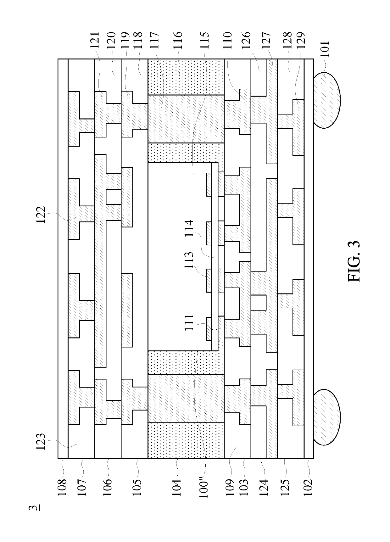
This patent aims to provide a multi-band antenna package structure that solves interferences between different frequency bands and offers advantages of cost efficiency, flexibility, scalability, small size, thin thickness, and light weight. This structure can be used for various communication devices such as frequency converters or encrypted communication devices.

Problems solved by technology

However, the wire-bonding not only significantly causes power consumption the radio frequency signal, but also occupies a large space due to the electrode pads for obtaining high quality input / output.
However, the package structure is not a stacked package structure which electrically connects a multi-band antenna with a system, and compared with the current advance manufacturing process, the manufacturing process of the package structure is not steady, such as, shapes of the through mold compound vias are discordant, and non-contact joints occur due to the effect of the warpage.

Method used


Image

  • Multi-band antenna package structure, manufacturing method thereof and communication device
  • Multi-band antenna package structure, manufacturing method thereof and communication device
  • Multi-band antenna package structure, manufacturing method thereof and communication device

Examples


Embodiment Construction

[0060]To make it easier for the examiner to understand the objects, characteristics and effects of this present disclosure, embodiments together with the attached drawings for the detailed description of the present disclosure are provided.

[0061]The 5th generation (5G) mobile communication system has technical characteristics of a heterogeneous network, a multiple input multiple output (MIMO) and beamforming control and an adoption of microwave. The 5G mobile communication system adopt a channel for a multi-mode module which supports three frequency bands. Furthermore, the three-dimensional integrated circuit (3D IC) stacked package technique has been developed well, and the development of the heterogeneous integration and micro-system is very important.

[0062]Accordingly, the present disclosure provides a multi-band antenna package structure which can integrate the radio frequency chip (having logic circuits and memories) and the antenna unit(s) in a stacked structure, so as to have...


PUM


Abstract

A multi-band antenna package structure includes a first redistribution layer; an integrated circuit layer, formed on the first redistribution layer, comprising at least one metal via, at least one metal pillar, an integrated circuit chip, and a molding layer, wherein the molding layer is used to fill openings formed by the metal via, the metal pillar and the integrated circuit chip which are disposed on the first redistribution layer, the metal via is electrically connected to one of the first metal patterns of the first redistribution layer; a second redistribution layer, formed on the integrated circuit layer; and a first antenna unit layer, comprising a first dielectric layer and third metal patterns formed in openings of the first dielectric layer, wherein at least one of the third metal patterns is electrically connected to one of the second metal patterns, and the third metal patterns form a first antenna unit.

Description

FIELD OF THE INVENTION[0001]The present disclosure relates to a multi-band antenna, and in particular to a multi-band antenna package structure, a manufacturing method of the multi-band antenna package structure and a communication device using the multi-band antenna package structure.BACKGROUND OF THE INVENTION[0002]The antenna is an important component of the communication device, which can radiate the radio frequency signal. One prior connection manner for electrically connecting an antenna system (i.e. front-end) with a chip system (i.e. back-end) is wire-bonding, wherein the antennae comprise an antenna disposed on a substrate and another one antenna disposed on a chip. However, the wire-bonding not only significantly causes power consumption the radio frequency signal, but also occupies a large space due to the electrode pads for obtaining high quality input / output.[0003]To reduce the usage of the wire-bonding, a design for integrating an antenna in a package structure has bee...

Claims


Application Information

Patent Timeline
IPC IPC(8): H01L23/66H01L23/538H01L23/31H01L23/552H01L21/683H01L21/56H01L21/48H01Q1/22
CPCH01L23/66H01L23/49827H01L23/5389H01L23/3128H01L23/5386H01L23/552H01L21/6835H01L21/565H01L21/568H01L21/4857H01L21/4853H01L21/486H01Q1/2283H01L2221/68359H01L24/20H01L2224/221H01L2924/3025H01L2223/6677H01L24/19H01L2924/1421H01Q1/247H01L23/5383H01L23/5226H01Q1/526H01Q21/28H01L2221/68345H01L2223/6688H01L2224/16235H01L2224/32225H01L2224/73204H01L2224/73253H01L2224/81005H01L2924/15311H01L2924/1533H01L2224/16225H01L2924/00H01Q1/38
Inventor CHIANG, CHING-WENKUAN, YEN-CHENGLIANG, CHIA-JENYU, CHIEN-TE
Owner NAT CHUNG SHAN INST SCI & TECH
Learn More