
An integrated heat exchange structure based on battery modules

A technology of battery module and heat exchange structure, which is applied to secondary batteries, electrochemical generators, circuits, etc., can solve the problem of insufficient heat exchange between the condensation section of the heat pipe and the cooling liquid, large volume of the liquid cooling channel, and increased cooling flow. and other problems, to achieve the effect of compact structure, light system weight, and strong heat exchange capacity

Active Publication Date: 2020-08-18
TSINGHUA UNIV
View PDF9 Cites 0 Cited by
  • Summary
  • Abstract
  • Description
  • Claims
  • Application Information

AI Technical Summary

Problems solved by technology

[0003] At present, the structural design of the combination of heat pipe and liquid cooling technology is still in the research stage. The structural basis of many experiments and simulations is based on a number of finned cylindrical heat pipes that guide the heat generated by the battery into the liquid cooling channel. The two are independent components and one-way liquid cooling. With the combination of channels, the heat exchange between the condensation section of the heat pipe and the cooling liquid is not sufficient. In order to enhance the heat exchange in the condensation section, it is necessary to increase the cooling flow rate to make the volume of the liquid cooling channel larger, and the downstream liquid has a higher heat dissipation capacity for the downstream heat pipe. Significantly lower than the upstream heat pipe, making the temperature uniformity between the heat pipes poor

Method used


Image

  • An integrated heat exchange structure based on battery modules
  • An integrated heat exchange structure based on battery modules
  • An integrated heat exchange structure based on battery modules

Examples


Embodiment Construction

[0020] Below in conjunction with accompanying drawing, structure of the present invention and specific embodiment are described further:

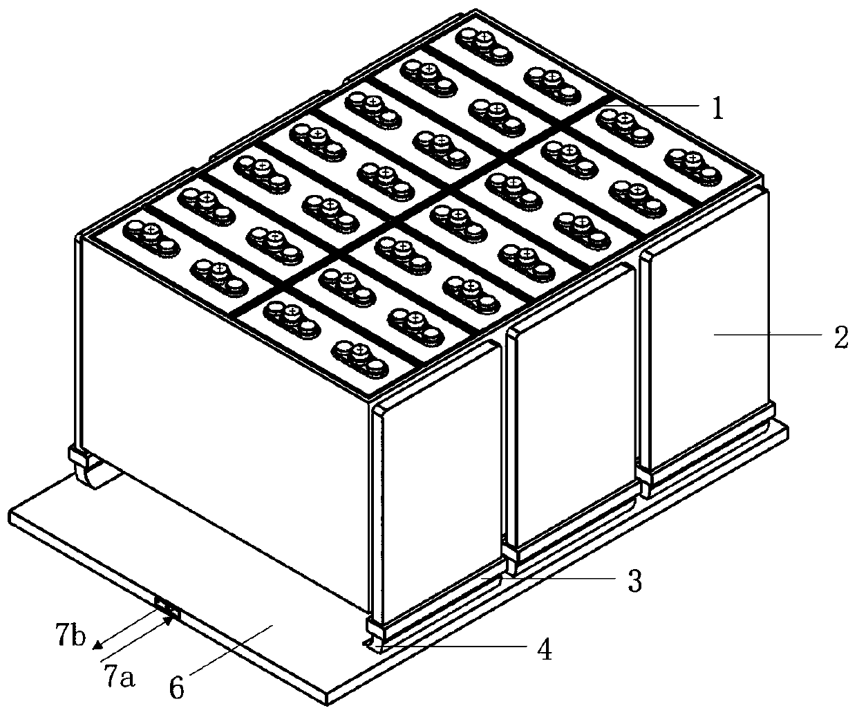
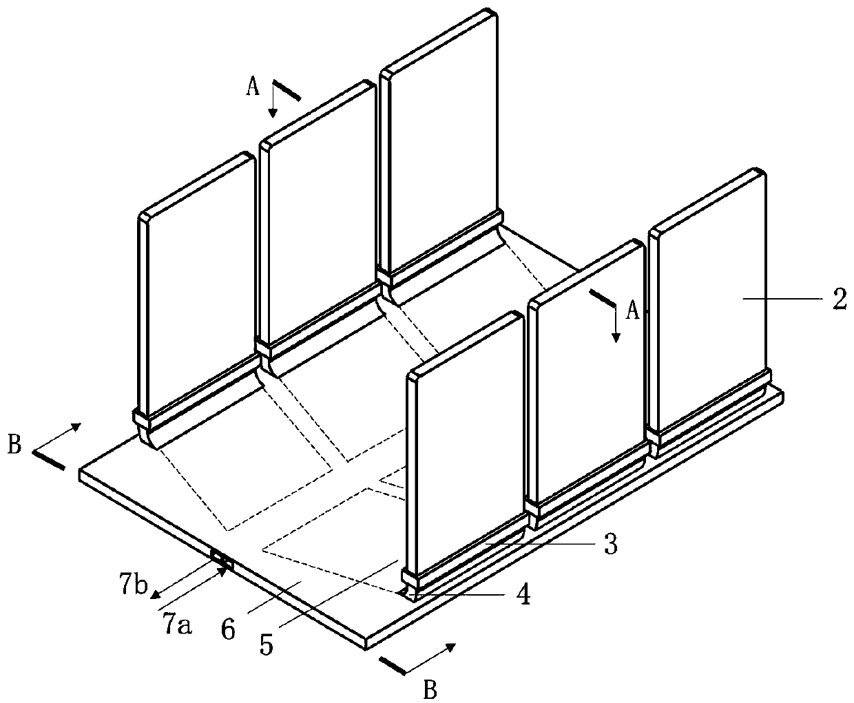
[0021] figure 1 An outline drawing of an integrated heat exchange structure based on a battery module provided by the present invention, the integrated heat exchange structure includes a cold plate 6 and at least one separate flat heat pipe, and the cold plate is arranged under the battery module 1; Each separated flat heat pipe is composed of heat pipe evaporating section 2, heat pipe bending section 4 and heat pipe condensing section 5. Its thickness is as thin as millimeters, and its material is aluminum or copper. Affected by gravity or the inclination of the heat pipe, it has the effect of micro-scale heat transfer enhancement and flat plate temperature uniformity. The separated flat heat pipe can also add a thermal insulation section between the evaporation section and the bending section to meet the long-distance heat conduction req...


PUM


Abstract

Disclosed is a battery module-based integrated heat exchange structure. The integrated heat exchange structure comprises a cold plate and at least one separated flat plate heat pipe; the cold plate isarranged below the battery module; heat pipe evaporation sections are tightly attached to the two sides of the battery module, and are connected with heat pipe condensation sections through heat pipebending sections and heat pipe connecting pieces; a plane is formed by enabling the parallelogram heat pipe condensation sections to be arranged in the cold plate, so that a double-flow-direction leaf vein flow channel is formed between the adjacent heat pipe condensation sections and between the heat pipe condensation sections and the side wall surface of the cold plate; and the flow directionsof fluids on the two sides of the center line are opposite, and a micro turbulent flow piece or a micro groove is additionally arranged in the flow channel. According to the integrated heat exchange structure, the structural design of combining the flat heat pipes and the cold plate technology is adopted, so that the heat pipe condensation sections and the cold plate are integrated, so that efficient heat dissipation can be achieved, the working temperature of the battery can be reduced, and the temperature uniformity of the battery module is improved; and in addition, the size is small, and the structure is compact, so that the technical defect that the temperature uniformity of the battery is poor due to the fact that the heat dissipation capacity of the heat pipes in the traditional heat pipe cooling mode is inconsistent is effectively overcome.

Description

technical field [0001] The invention relates to an integrated heat exchange structure of a battery module, belonging to the technical field of battery heat management and heat transfer. Background technique [0002] High-temperature enhanced heat dissipation and low-temperature rapid heating are the focus of power battery thermal management research, among which the enhanced heat transfer research of batteries is the frontier and hot spot. The current research methods mainly include phase change materials (PCM) based on the phase change process, heat conduction of heat pipes, and heat dissipation based on air cooling and liquid cooling. The phase change material PCM or heat pipe structure can significantly enhance the heat conduction of the battery and achieve uniform temperature. PCM uses its latent heat to absorb the heat generated by the battery, and improves its thermal conductivity by preparing PCM or adding foam metal, graphite and other materials, but there are defec...

Claims


Application Information

Patent Timeline
Patent Type & Authority Patents(China)
IPC IPC(8): H01M10/613H01M10/617H01M10/6552H01M10/6554H01M10/6556H01M10/6567
CPCH01M10/613H01M10/617H01M10/6552H01M10/6554H01M10/6556H01M10/6567Y02E60/10
Inventor 张扬军姚程宁丹聃诸葛伟林李志勇钱煜平
Owner TSINGHUA UNIV
Learn More