


Quick Research
Generate reliable direction feasibility study reports for your R&D in just a few steps.

Technical Q&A
Discover and master advanced knowledge NOW. Basics, ideas, possibilities, all at once.

Find Solutions
As an expert in R&D theories, this can generate solutions to your technical problems instantly.

Evaluate Feasibility
Analyze your overall solution with one click, know your potential R&D risks in advance.

Monitor Landscape
Get weekly tech updates, stay abreast of the latest tech innovations and key insights.
Treatment method for cracks at corners of nickel-containing continuous casting slab
A treatment method and a technology for corners, which are applied in the direction of aluminothermic welding equipment, welding equipment, metal processing equipment, etc., can solve the problems of reducing the cleaning area and surrounding steel base, affecting the quality and performance of steel, and waste of blanks, etc., to achieve improvement Processing efficiency and stability, optimization of crack processing effect, and improvement of billet yield
- Summary
- Abstract
- Description
- Claims
- Application Information
AI Technical Summary
Problems solved by technology
Method used
Image


Examples
Embodiment 1
[0061] The conditions for applying this method to medium and high alloy continuous casting slabs are as follows:
[0062]
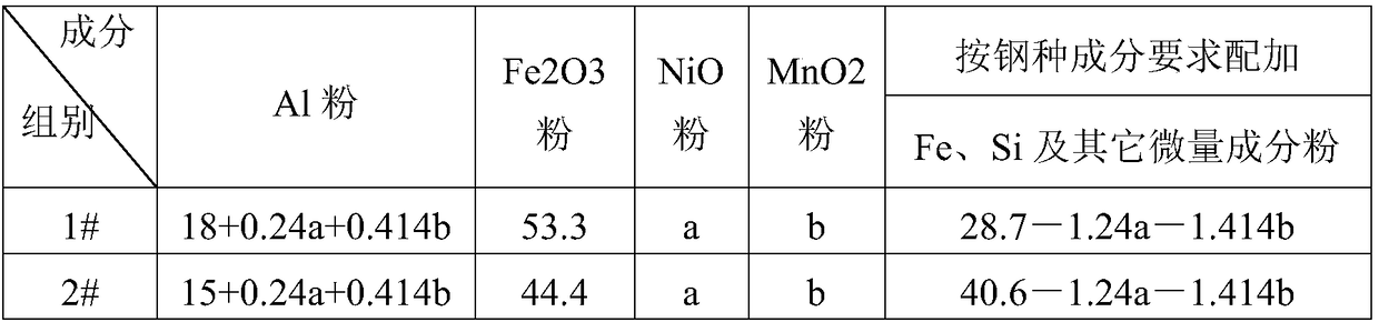
[0063] Based on the above conditions, the composition of thermite used is as follows:
[0064]
[0065]
[0066] It takes 6 minutes to fabricate the cracked area at the corner. When the magnesium strip is ignited, the surface temperature of the slab is 484°C. After the reaction is self-sustaining and the surface of the reaction area is purged, the cracked area is well fused. The total treatment time is 13 minutes. After slow cooling No secondary cracks were seen, and the metal sample after the reaction was taken for detection, and the composition was as follows:
[0067]
[0068] It can be seen from the above table that after the aluminothermic reaction, the cost of the reaction product is basically the same as that of the steel base, and meets the requirements of the steel composition. It is consistent with the thermite reaction design princ...
Embodiment 2
[0071] The conditions for applying this method to medium and high alloy continuous casting slabs are as follows:
[0072]
[0073] Based on the above conditions, the composition of thermite used is as follows:
[0074]
[0075] It takes 8 minutes to fabricate the cracked area at the corner. When the magnesium strip is ignited, the surface temperature of the slab is 271°C. After the reaction is self-sustaining and the surface of the reaction area is purged, the cracked area is well fused. The total treatment time is 13 minutes. After slow cooling No secondary cracks were found, and the reacted metal sample was taken for testing. The composition is as follows:
[0076]
[0077]
[0078] It can be seen from the above table that after the aluminothermic reaction, the cost of the reaction product is basically the same as that of the steel base, and meets the composition requirements of the steel type. The contents of Mn and Ni in the reactant are slightly higher than th...
Embodiment 3
[0081] The conditions for applying this method to medium and high alloy continuous casting slabs are as follows:
[0082]
[0083] Based on the above conditions, the composition of thermite used is as follows:
[0084]
[0085] It takes 7 minutes to fabricate the cracked area at the corner. When the magnesium strip is ignited, the surface temperature of the slab is 425°C. After the reaction is self-sustaining and the surface of the reaction area is purged, the cracked area is well fused. The total treatment time is 15 minutes. After slow cooling No secondary cracks were found, and the reacted metal sample was taken for testing. The composition is as follows:
[0086]
[0087] It can be seen from the above table that after the aluminothermic reaction, the cost of the reaction product is basically the same as that of the steel base, and meets the steel composition requirements, and the carbon content meets the minimum requirements
[0088] The continuous casting slab w...
PUM
 Abstract
Description
Claims
Application Information
 - R&D Engineer
- R&D Manager
- IP Professional
- Industry Leading Data Capabilities
- Powerful AI technology
- Patent DNA Extraction
Browse by: Latest US Patents, China's latest patents, Technical Efficacy Thesaurus, Application Domain, Technology Topic, Popular Technical Reports.
© 2024 PatSnap. All rights reserved.Legal|Privacy policy|Modern Slavery Act Transparency Statement|Sitemap|About US| Contact US: help@patsnap.com