
Oily water treatment equipment

A kind of water treatment equipment and oil-water separation technology, which is applied in the field of water treatment, can solve the problems of ineffective treatment of emulsified oil, ineffective treatment of emulsified oil, weak impact load resistance, etc., to achieve treatment residence time, reduce equipment operation risk, Improve the effect of shock load resistance

Pending Publication Date: 2018-10-23
汪传发
View PDF0 Cites 0 Cited by
  • Summary
  • Abstract
  • Description
  • Claims
  • Application Information

AI Technical Summary

Problems solved by technology

[0013] The second is that the impact load resistance is weak: the current technology is to set the oil-water separation layer interface at a fixed liquid level elevation, set the oil discharge pipe on the oil layer on the interface, and set the drain port at the lower part of the interface layer
When the processing load is heavy, the actual oil-water interface layer is higher than the set oil-water interface layer. At this time, the height of water and oil exceeds the set oil-water interface layer. At this time, the oil discharge will cause the water content of the oil outlet to decrease. Too high, not conducive to recycling
[0014] The third is that the emulsified oil cannot be effectively treated
Both static sedimentation separation and dynamic enhanced separation cannot effectively treat the emulsified oil in wastewater, resulting in excessive drainage water quality
[0015] It can be seen that the above-mentioned existing oily water treatment equipment obviously still has inconvenience and defects in structure, method and use, and needs to be further improved urgently

Method used


Image

  • Oily water treatment equipment
  • Oily water treatment equipment

Examples


Embodiment 1

[0043] This embodiment provides an oil-containing water treatment equipment, which can be used for the oil-water separation of catering wastewater after slag removal treatment; it can also be directly used for the oil-water treatment of industrial wastewater containing no or less solids.

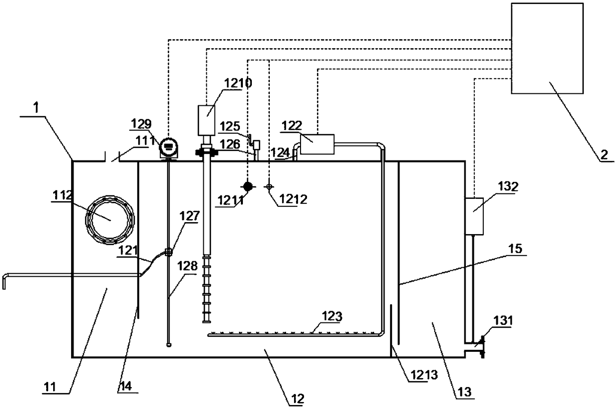
[0044] Such as figure 1 As shown, the oily sewage treatment equipment includes an oil-water separation tank 1, which includes a diversion tank 11, an enhanced separation tank 12, and a drainage tank 13, which are independent of each other and communicate with the lower part in sequence; the upper part of the diversion tank 11 is provided with an inlet The water outlet 111; the enhanced separation bin 12 is provided with an oil discharge pipe 121; the lower part of the drainage bin 13 is provided with a water outlet pipe 131.

[0045] When working, the oily sewage enters the diversion tank 11 from the water inlet 111, flows from top to bottom under the diversion effect of the diversion tank 11 and ...

Embodiment 2

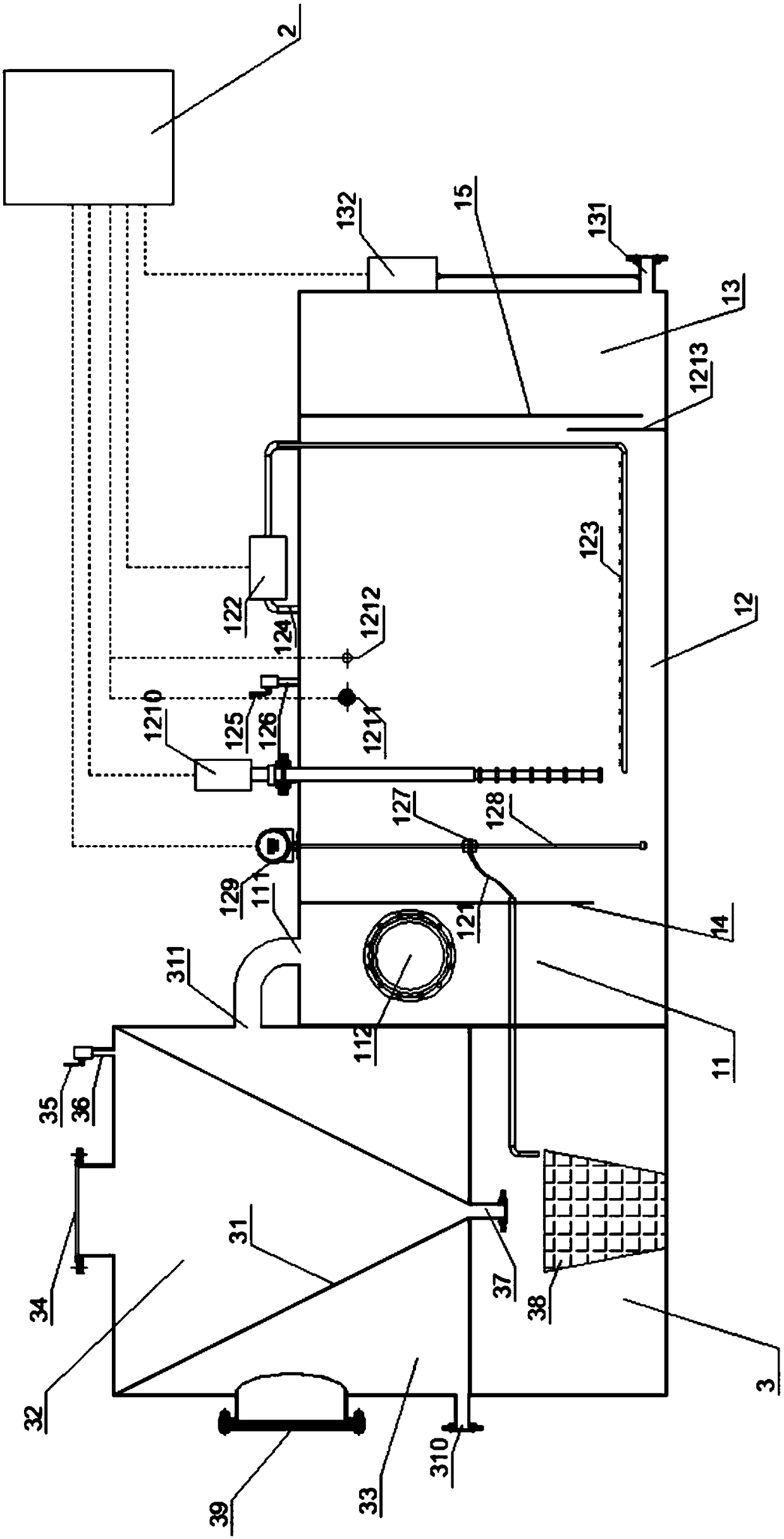
[0061] The oily sewage treatment equipment of this embodiment, on the basis of embodiment 1, has multiple pre-treatment steps in the process, and adds a solid-liquid separation bin to the physical structure, which is mainly used to treat wastewater containing solids. Such as slag removal and oil separation treatment of catering wastewater.

[0062] Specific as figure 2 As shown, the water outlet 311 of the solid-liquid separation bin 3 is in communication with the water inlet 111 of the diversion bin 11, and the water outlet 311 of the solid-liquid separation bin 3 is higher than the water inlet 111 of the diversion bin 11. Through the above arrangement, firstly, the moisture in the separated solid impurities can be reduced by gravity flow; secondly, the solid impurities can be discharged by gravity flow.

[0063] Specifically, the solid-liquid separation bin 3 includes an upper and lower part, the upper part is divided into an inner and an outer chamber by a solid-liquid separat...


PUM


Abstract

The invention belongs to the field of water treatment and discloses oily water treatment equipment. The oily water treatment equipment comprises an oil-water separation chamber which comprises a reinforced separation chamber, the reinforced separation chamber is provided with a water inlet, a water outlet, an oil outlet pipe and an aeration system, and the aeration system comprises an aerator andan aeration device connected with the aerator. An air cavity in the upper portion of the reinforced separation chamber is communicated with an air inlet of the aerator, the aeration device is arrangedin a water cavity in the lower portion of the reinforced separation chamber, and the reinforced separation chamber is further provided with an air inlet pipe with an air inlet valve. An aeration system is arranged in the reinforced separation chamber, the air outlet pipe on the upper portion of the aeration system is communicated with the aerator, and accordingly the problem of odor diffusion canbe effectively solved to further prevent environmental pollution; by arrangement of an ultrasonic demulsification device, grease in a highly emulsified stage can be effectively separated; by arrangement of the adjustable oil outlet pipe, impact load resistance is greatly improved, and suitableness for popularization and application is realized.

Description

Technical field [0001] The invention relates to the field of water treatment, in particular to an oily water treatment equipment. Background technique [0002] In recent years, with the growth of the national economy and the rapid development of the catering industry, the amount of wastewater discharged by it has become larger and larger. Due to the high concentration of animal and vegetable oils and a large amount of suspended solids in the wastewater, it has become an important source of water pollution. . [0003] Therefore, the treatment of oily wastewater in the catering industry can not only protect the ecological environment, but also reduce the burden of urban sewage treatment plants, which has obvious environmental and economic benefits. The oily wastewater of the catering industry contains high levels of pollution, and the main pollutants are animal and vegetable oils and suspended solids. At present, in the catering industry, the wide application of detergent makes the...

Claims


Application Information

Patent Timeline
IPC IPC(8): C02F1/40C02F1/20C02F1/24C02F1/36
CPCC02F1/20C02F1/24C02F1/36C02F1/40
Inventor 汪传发
Owner 汪传发
Learn More