Gas compressor circle-arc tooth rotor blade vibration fatigue test fixture

A rotor blade and vibration fatigue technology, which is applied in the field of fatigue performance test fixtures, can solve problems such as high replacement rate of vibration fatigue fixtures, inability to transfer vibration system energy, and difficulty in finding the cause of test failure, so as to facilitate the adjustment of the excitation point position and improve Energy transfer efficiency, vibration sensitive effect

Inactive Publication Date: 2018-08-14
CHINA HANGFA GUIZHOU LIYANG AVIATION POWER CO LTD
View PDF8 Cites 2 Cited by
  • Summary
  • Abstract
  • Description
  • Claims
  • Application Information

AI Technical Summary

Problems solved by technology

[0004] 1. During the vibration fatigue test, due to the relatively concentrated stress at the sudden change of the chuck position, the cracks at the stress concentration will increase as time goes on, and the bearing capacity of the fixture will decrease until it breaks, resulting in the termination of the test
Second, due to the hidden fracture of the chuck during the experiment but not falling off obviously, the energy of the vibration system cannot be transmitted to the test blade, so the data collected by the test system is a constant, and the data acquisition fails. This hidden fracture Hardest to find cause of test failure
[0005] 2. The positioning block and the pressing block of the fixture are connected by connecting bolts, and the blades are compressed by tightening the screws at the end of the fixture. However, in the design process of the experimental fixture, the connecting bolts are perpendicular to the vibration direction, forming a strong transverse shear force , because the structural stress of the connecting bolt itself is very concentrated, and it bears high energy load for a long time, so the connecting bolt is very easy to break in the test
[0006] Due to various disadvantages in the structural design of split horizontal vibration fatigue fixtures, its use effect and life are seriously affected, which makes the replacement rate of vibration fatigue fixtures extremely high, increases production costs, and seriously restricts the production schedule of blades

Method used


Image

  • Gas compressor circle-arc tooth rotor blade vibration fatigue test fixture
  • Gas compressor circle-arc tooth rotor blade vibration fatigue test fixture
  • Gas compressor circle-arc tooth rotor blade vibration fatigue test fixture

Examples


Embodiment Construction

[0031] The technical solution of the present invention is further described below in conjunction with the accompanying drawings, but the scope of protection is not limited to the description.

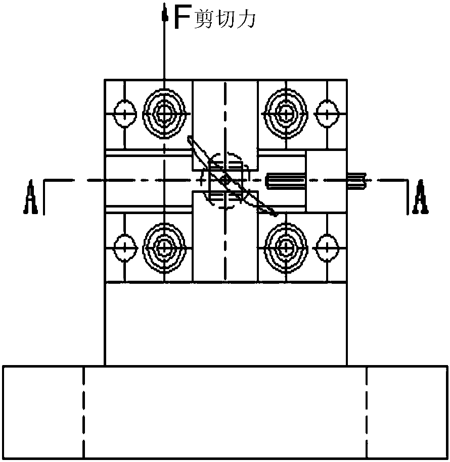
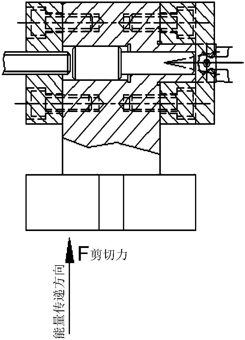
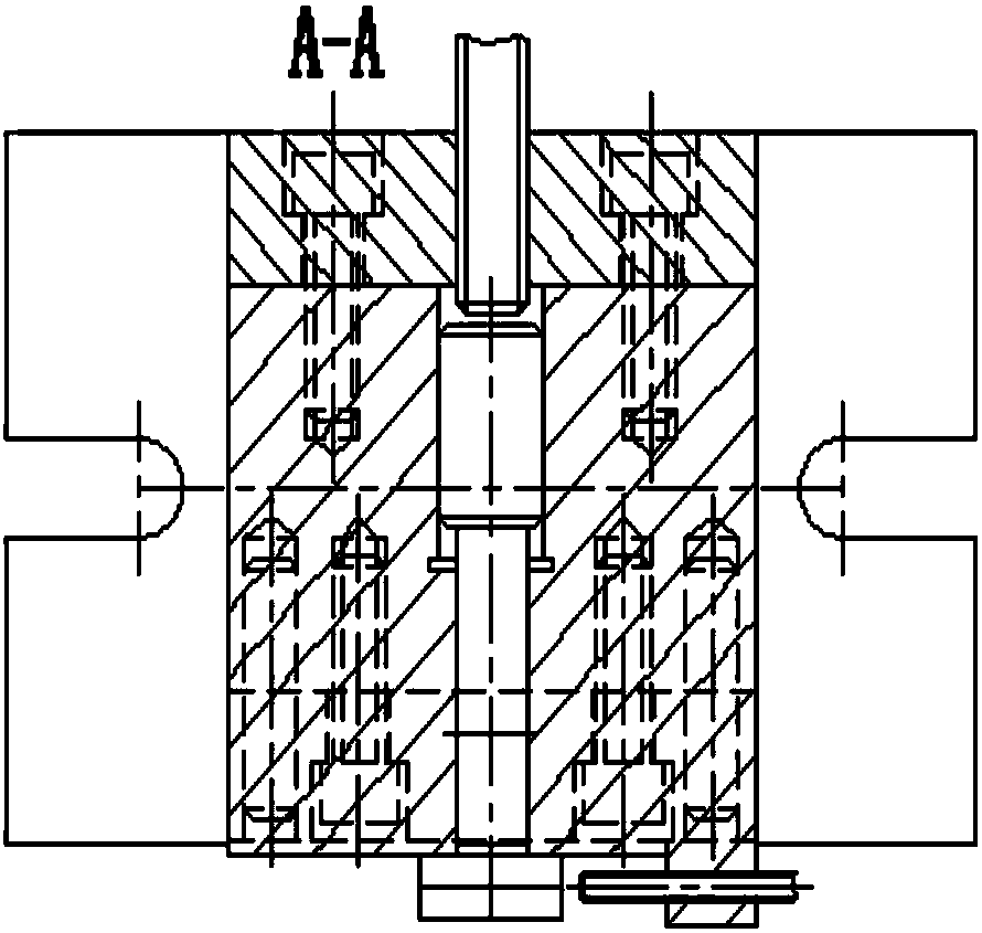
[0032] figure 2 It is the structural diagram of the elevation angle fixture of the present invention, the arc-tooth tenon chuck 2 is fixed on the base 1 with an inclined angle at the upper end, fixed with connecting bolts 5, and two positioning pins 4 are used to ensure the arc-tooth tenon chuck 2 position on base 1 (eg Figure 4 , that is, the arc-tooth tenon chuck 2 is fixed on the arc-tooth tenon chuck mounting surface 3 on the upper side of the base 1), and the blade body is placed in a horizontal position through the angle designed by the base 1 with an elevation angle, so that the blade body The vibration is sensitive, which is convenient for the vibration system to collect effective data. At the same time, the arc-tooth tenon chuck 2 is clamped on the base 1 with an elevation a...


PUM


Abstract

The invention discloses a gas compressor circle-arc tooth rotor blade vibration fatigue test fixture. The gas compressor circle-arc tooth rotor blade vibration fatigue test fixture comprises a pedestal and a circle-arc tooth tenon chuck which is formed by combining an upper positioning block with a lower positioning block. An included angle is formed between the chuck installation surface of the pedestal and the connecting surface of the lower end of the pedestal and a shock excitation table. The effect that the energy releasing directions of blade bodies and the shock excitation table are perpendicular can be guaranteed through the included angle. By means of the gas compressor circle-arc tooth rotor blade vibration fatigue test fixture, the phenomena that vibration transmission of the fixture is insensitive in the vibration fatigue testing process, breakage happens between connecting pieces, the vibration transmission is incontinuous or is stopped suddenly, and accordingly the vibrational frequency value is abnormally fluctuated or the frequency value detected by a monitor is a constant are effectively avoided; the design mode of an existing split horizontal-type structural vibration fatigue test fixture is changed particularly, the number of the connecting pieces between fixture parts is reduced, the structure is simple and portable, clamping can be achieved easily, vibration transmission is sensitive, and the frequency monitor can stably and reliably detect the real effective performance experimental data of gas compressor circle-arc tooth rotor blades.

Description

technical field [0001] The invention relates to a fixture for fatigue tests, in particular to a fatigue performance test fixture suitable for one to nine stages of rotor blades made of aero-engine titanium alloys and high-temperature alloys, and the mode shape of the blades is first-order bending vibration. Background technique [0002] At present, most of the vibration fatigue test fixtures are made of No. 45 steel, which adopt multi-part split horizontal structure design, and are connected and compressed by bolts. The disadvantage is that the stress concentration of the split horizontal structure fixture is serious, and the stress concentration part of the chuck is close to the The shear force generated by the UD electromagnetic vibration table is 90°, and it is very easy to break during the vibration test, which seriously affects the service life of the fixture. At the same time, the split horizontal structure design has a large volume, poor overall rigidity, and insensit...

Claims


Application Information

Patent Timeline
Patent Type & Authority Applications(China)
IPC IPC(8): B25B11/00G01M15/02G01M13/00
CPCB25B11/00G01M13/00G01M15/02
Inventor 冯志徐华王成霖陈洲能吴凡卫广龙
Owner CHINA HANGFA GUIZHOU LIYANG AVIATION POWER CO LTD
Why Eureka
Try Eureka