CO cryogenic separation system using double circulation and separation method thereof

A technology of cryogenic separation and separation method, which is applied in CO cryogenic separation system and its separation field, which can solve the problems of low efficiency of CO compressor and expander, large amount of venting at the start-up stage, and long purification time, etc., so as to reduce venting The effect of small amount, low investment cost, good economic benefits and environmental protection benefits

Active Publication Date: 2017-11-07
四川蜀道装备科技股份有限公司
View PDF7 Cites 7 Cited by
  • Summary
  • Abstract
  • Description
  • Claims
  • Application Information

AI Technical Summary

Problems solved by technology

[0003] Chinese invention patent CN 100427862 C "method and equipment for producing carbon monoxide by low-temperature distillation" and CN101823709 B "separation of carbon monoxide from a gas mixture containing carbon monoxide" both use pure CO Compression and refrigeration cycles, in view of the low efficiency and high technical requirements of the CO compressor and expander, the energy consumption and investment of this process are relatively large, and the start-up and purification of the device take a long time, and the amount of venting during the start-up stage is large
[0004] Chinese Invention Patent CN 104326472 B "A system and method for producing CO by a nitrogen cycle process" adopts pure nitrogen compression and refrigeration cycle, although the nitrogen compressor and expansion The efficiency of the machine is relatively high and the technology is mature, but when this process is used in occasions that require fine removal of methane and nitrogen, it has the disadvantage of high rectification energy consumption

Method used


Image

  • CO cryogenic separation system using double circulation and separation method thereof
  • CO cryogenic separation system using double circulation and separation method thereof
  • CO cryogenic separation system using double circulation and separation method thereof

Examples


Embodiment 1

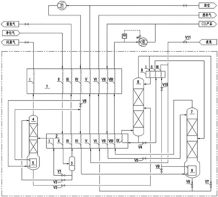
[0039] Embodiment one: if figure 1 As shown, a CO cryogenic separation system adopting double circulation, it includes main heat exchanger A1, main heat exchanger B2, low temperature separator 3, hydrogen stripper 4, hydrogen stripper bottom evaporator 5, Denitrification tower 6, demethanizer 7, demethanizer bottom evaporator 8, denitrification tower top condenser 9, CO compressor 10 and circulating nitrogen compressor 11; containing CO, hydrogen and a small amount of methane, nitrogen, The purified gas of argon is connected with the inlet of the main heat exchanger A1 flow channel II and the main heat exchanger B2 flow channel II in turn, and the outlet of the main heat exchanger B2 flow channel II is connected with the inlet of the low temperature separator 3, and the low temperature separator The gas phase outlet of 3 is connected with the inlet of the main heat exchanger B2 flow channel III and the main heat exchanger A1 flow channel III in turn, and the liquid phase outle...

Embodiment 2

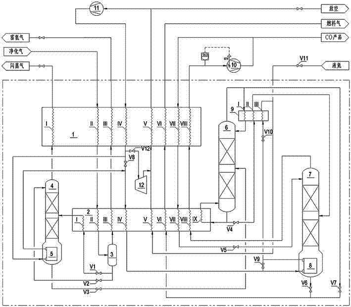
[0063] Embodiment 2: as figure 2 As shown, the difference between this embodiment and Embodiment 1 is that a branch pipe is also provided on the passage connecting the decompression valve V8 to the outlet of the flow channel IV of the main heat exchanger A1, and the branch pipe is connected to the decompression valve V12 and then connected to On the inlet of the turboexpander 12, the outlet of the turboexpander 12 is connected to the pipe connecting the flow passage V of the main heat exchanger B2 and the flow passage V of the main heat exchanger A1. That is, a stream of stream is added at the outlet of medium-pressure nitrogen out of main heat exchanger A1 flow channel IV, and then sent to the inlet of turboexpander 12 after passing through decompression valve V12, and the outlet of turboexpander 12 is connected with the low-pressure nitrogen main pipe. When the device is started or the cooling capacity is insufficient, the turbo expander 12 is used to obtain the cooling cap...

Embodiment 3

[0064] Embodiment 3: as image 3 As shown, the difference between this embodiment and Embodiment 1 is: the inlet node of the evaporator at the bottom of the hydrogen stripper and the outlet node of the evaporator at the bottom of the hydrogen stripper are arranged at the flow channel IIA of the main heat exchanger A1 and the main The pipeline connected to flow channel IIB of heat exchanger B2, and a pressure reducing valve V8A is set between the inlet node of hydrogen stripper bottom evaporator 5 and the outlet node of hydrogen stripper bottom evaporator 5, and the hydrogen stripper bottom evaporator The evaporator 5 inlet node is connected to the inlet of the hydrogen stripper bottom evaporator 5 through a pipeline, and the hydrogen stripper bottom evaporator 5 outlet node is connected to the hydrogen stripper bottom evaporator 5 outlet through a pipeline. That is, the heat source of the evaporator 5 at the bottom of the hydrogen stripper is purified gas, which can reduce the...


PUM


Abstract

The invention discloses a CO cryogenic separation system using double circulation. The CO cryogenic separation system comprises main heat exchangers, a low-temperature separator, a hydrogen stripping tower, a denitriding tower, a demethanizer, a CO compressor and a circulation nitrogen compressor. The invention further discloses a separation method of the CO cryogenic separation system using double circulation. The method includes the processing steps of heat transfer, dehydrogenation, denitrification, demethanation, CO compression cycle, nitrogen compression refrigeration cycle and the like. The CO cryogenic separation system using double circulation and the separation method thereof have the beneficial effects that the double-circulation process of CO compression and nitrogen compression is adopted, and the dual advantages that rectification energy consumption of CO compression cycle is low and compression energy consumption and investment of nitrogen cycle are low are given into play. A heat source of a rectifying tower evaporator and a cold source of a condenser are optimized, and rectification loads can be controlled reliably and stably. Starting and purifying time of the device can further be shortened, and the evacuation amount at the starting stage is decreased. Energy consumption is low, the starting speed is high, the investment can be reduced, and the quantity of emissions is small. The general trend of energy saving and cost reduction are met, and the economic benefits and environmental protection benefits are good.

Description

technical field [0001] The invention relates to the field of cryogenic gas separation, in particular to a double-cycle CO cryogenic separation system and a separation method thereof. Background technique [0002] CO is an important raw material gas for oxo synthesis, and almost all organic chemicals can be prepared from CO. At present, the synthesis gas for producing CO mainly comes from pressurized coal gasification or natural gas / naphtha steam reforming. In addition to CO and hydrogen, the synthesis gas produced by coal gasification also contains a small amount of methane, nitrogen and argon. In view of the very high purity requirements (≥98.5%) of raw material CO in the production of chemical products such as ethylene glycol, acetic acid and dimethyl diamide, it is necessary to mix hydrogen, methane, nitrogen and argon in the synthesis gas remove. Cryogenic separation technology has mature technology, stable operation, large processing capacity, high product purity and ...

Claims


Application Information

Patent Timeline
Patent Type & Authority Applications(China)
IPC IPC(8): F25J3/02
CPCF25J3/0261F25J2200/10F25J2270/02F25J2270/12F25J2200/40F25J3/0257F25J2270/14F25J2270/42F25J3/0223F25J3/0252F25J2205/04F25J2270/24F25J2200/70F25J2200/76F25J3/0233F25J2200/72F25J2210/42
Inventor 曹卫华文向南
Owner 四川蜀道装备科技股份有限公司
Why Eureka
Try Eureka