
Odorant for fuel gases for anion membrane fuel cells, fuel gas and power generation system using anion membrane fuel cell

A fuel gas and fuel cell technology, applied in fuel cell additives, fuel cells, solid electrolyte fuel cells, etc., can solve problems such as practical obstacles, air pollution, oxidation catalyst poisoning, etc., and achieve the effect of significant effect and low threshold.

Inactive Publication Date: 2017-08-18
TOKUYAMA CORP
View PDF4 Cites 0 Cited by
  • Summary
  • Abstract
  • Description
  • Claims
  • Application Information

AI Technical Summary

Problems solved by technology

[0005] However, with regard to these compounds, there has been a problem that since fuel gas is combusted to generate sulfur oxides, this becomes a cause of air pollution; or in the case of fuel cells, odorants in fuel gas Poisoning the oxidation catalyst of the fuel cell, significantly deteriorating its performance, etc.
However, many problems as mentioned above become practical obstacles

Method used


Image

  • Odorant for fuel gases for anion membrane fuel cells, fuel gas and power generation system using anion membrane fuel cell
  • Odorant for fuel gases for anion membrane fuel cells, fuel gas and power generation system using anion membrane fuel cell
  • Odorant for fuel gases for anion membrane fuel cells, fuel gas and power generation system using anion membrane fuel cell

Examples


Embodiment 1~10

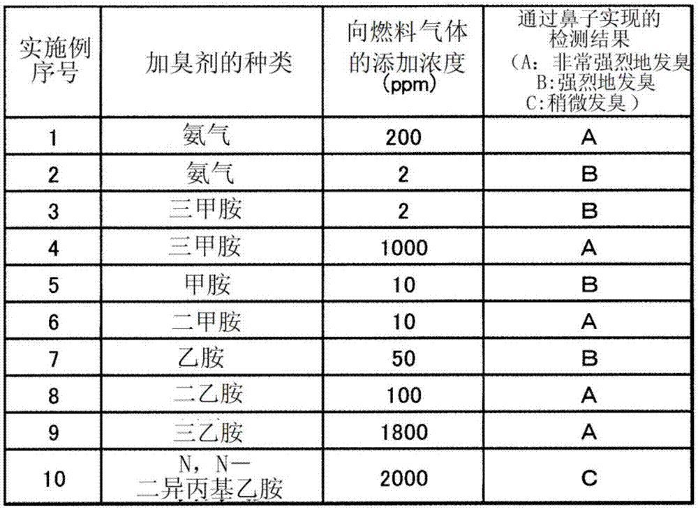
[0062]Various concentrations of the odorant of the present invention shown in Table 1 were added to hydrogen as fuel gas. These odorant-added fuel gases were released into the atmosphere at 1 ml / min. The effectiveness as an odorant was confirmed by detecting the presence or absence of the odor with the nose from above 50 cm.

[0063] [Table 1]

[0064] Table 1

[0065]

Embodiment 11

[0067] Using the fuel gas of Example 1, instead of detecting with a nose, the same experiment as in Examples 1 to 10 was performed by placing pH test paper wetted with water. The pH test paper before the experiment starts is yellow. After leaving for 30 minutes, the change of color was confirmed, and the pH test paper changed to blue which shows alkalinity. It was shown that the odorant of the present invention has the characteristic of being detectable by methods other than odor.

Embodiment 12

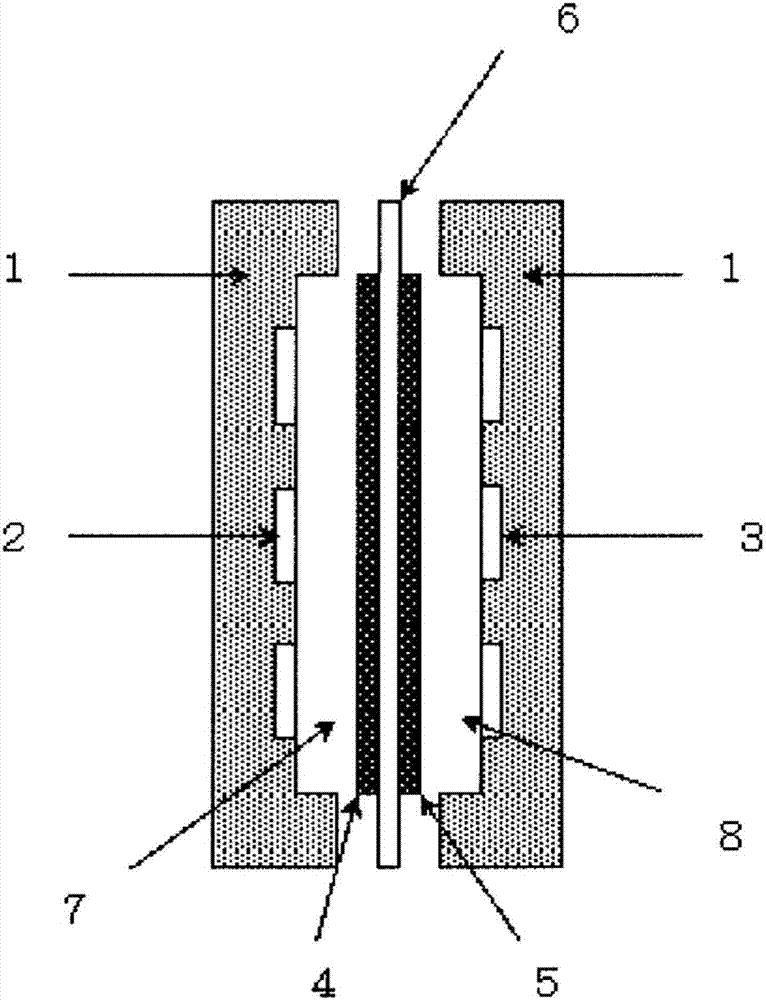
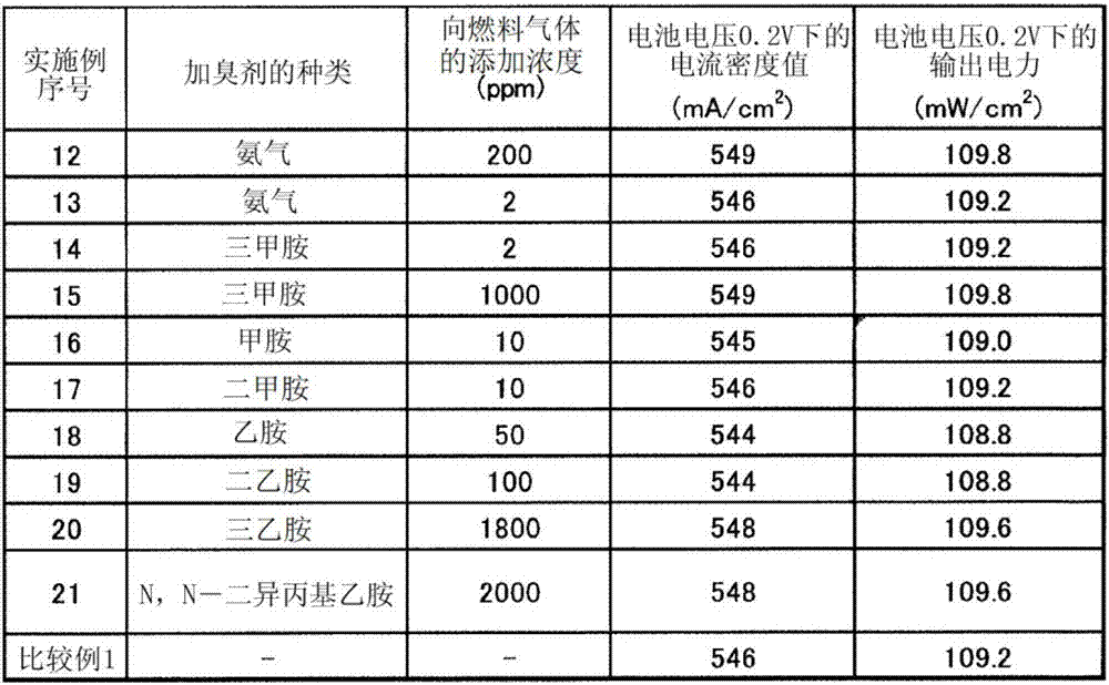
[0069] An anion exchange resin binder (manufactured by Tokuyama Co., Ltd.) and a carbon-supported platinum catalyst (manufactured by Tanaka Precious Metals Co., Ltd.) were coated on both sides of the center of an 8 cm square anion exchange membrane (manufactured by Tokuyama Co., Ltd.) in a square of 2.3 cm. mixture to produce a membrane electrode assembly. The catalyst portion was sandwiched between two 2.3 cm square carbon porous plates (manufactured by SGL Co., Ltd.) with a thickness of about 200 μm, and installed in a commercially available fuel cell (manufactured by NF Circuit Design Co., Ltd.). The fuel gas of Example 1 was supplied to the anode side at 50° C. at 50 ml / min. Air humidified to a humidity of 100% was supplied to the cathode side at 50°C. The battery temperature was set to 50°C. Connect to an electronic load device (manufactured by NF Circuit Design Co., Ltd.), and record the current density value after 2 hours of power generation at a battery voltage of 0....


PUM

PropertyMeasurementUnit
specific surface areaaaaaaaaaaa

Abstract

The present invention aims to provide an odorant for fuel gases for anion membrane fuel cells, which does not generate a harmful sulfur compound after combustion and does not deteriorate the performance of a fuel cell, while enabling leakage detection at low concentrations, and which enables detection of leakage of a gas by a means other than odor, for example, by visual observation. The odorant for fuel gases for anion membrane fuel cells, imparts a fuel gas with an odor, and is characterized in that the odorant contains at least one or more substances selected from the group consisting of ammonia, trimethylamine, triethylamine, N,N-diethylmethylamine, N,N-dipropylmethylamine, N,N-dipropylethylamine, N,N-diisopropylmethylamine, N,N-diisopropylethylamine, dimethylamine, diethylamine, dipropylamine, ethylmethylamine, propylmethylamine, propylethylamine, methylamine, ethylamine and propylamine.

Description

technical field [0001] The present invention relates to an odorant for fuel gas that adds an odor to fuel gas used in an anion membrane fuel cell. Also, the present invention relates to a power generation system using an anion membrane fuel cell using the fuel gas. Background technique [0002] Fuel gas has become an indispensable substance in industrial production and ordinary households. As a method of utilizing the fuel gas, for example, it is mixed with air or oxygen and combusted to extract thermal energy, or electrical energy is extracted by a fuel cell. [0003] Fuel gas has the convenience of being able to be introduced anywhere as long as there are gas pipes, but on the other hand, when leaking due to deterioration of the pipes, etc., it may not be visually confirmed. Since leaked fuel gas mixed with air may also cause an explosion accident, it is very important to detect this and prevent it before it happens. [0004] Conventionally, for this purpose, fuel gas h...

Claims


Application Information

Patent Timeline
Patent Type & Authority Applications(China)
IPC IPC(8): H01M8/04664H01M8/22
CPCY02E60/50H01M8/0662H01M8/1004H01M8/04H01M8/10C01B3/02C01C1/02G01M3/00G01N21/80H01M4/926H01M8/04671H01M2008/1095
Inventor 根岸贵幸渡边伸
Owner TOKUYAMA CORP
Learn More