
Preparation method for composite coating of cutter

A composite coating and cutting tool technology, which is applied in the coating, metal material coating process, ion implantation plating, etc., can solve the problems of poor bonding force of the membrane base, limited membrane application range, and low metal ionization rate.

Active Publication Date: 2017-05-31
GUANGDONG UNIV OF TECH
View PDF7 Cites 9 Cited by
  • Summary
  • Abstract
  • Description
  • Claims
  • Application Information

AI Technical Summary

Problems solved by technology

[0003] Magnetron sputtering and arc ion plating are the two mainstream technologies for preparing tool coatings at this stage, but there are various defects on the surface of the arc ion plating film, including droplets, hard particles, and pinholes, which are extremely limited. The scope of application of the membrane
The traditional magnetron sputtering technology has many advantages such as low-temperature deposition, smooth surface, and no particle defects, but most of the sputtered metals exist in the atomic state, and the metal ionization rate is low, resulting in poor adhesion of the film base and easy peeling of the coating. fail

Method used


Image

  • Preparation method for composite coating of cutter
  • Preparation method for composite coating of cutter
  • Preparation method for composite coating of cutter

Examples


preparation example Construction

[0024] The embodiment of the invention discloses a method for preparing a tool coating, including the following steps:

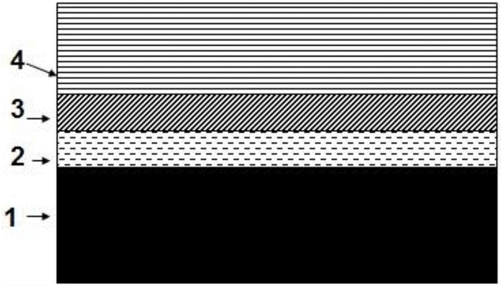
[0025] A). Clamp the cleaned tool on the workpiece holder of the high-power pulsed magnetron sputtering apparatus, and vacuum, the vacuum degree of the cavity of the high-power pulsed magnetron sputtering apparatus is higher than (1~5)×10 -3 When Pa, turn on the heater to a temperature of 300~500℃, the rotation speed of the workpiece holder is 2~5rpm, when the vacuum degree is (1.2~5.5)×10 -3 When Pa, adjust the electric heater to a temperature of 200~400℃;

[0026] B) Pass inert gas into the cavity of the high-power pulse magnetron sputtering apparatus, turn on the bias power supply to perform glow cleaning on the tool, the vacuum degree is 0.3~0.9Pa, and the bias voltage is 800~1200V;

[0027] C) After the glow cleaning is finished, adjust the vacuum of the cavity of the high-power pulse magnetron sputtering apparatus to (1-9)×10 - 1 Pa, turn on the high-power pul...

Embodiment 1

[0037] Clean the hard alloy tool workpiece to be coated with alcohol and acetone, dry it with an air gun, and place it on the substrate holder in the cavity; start to pre-vacuum, when the vacuum degree is higher than 3×10 -3 At Pa, start to turn on the heater to remove the gas attached to the inner wall of the vacuum chamber and the workpiece holder. The temperature is controlled at 400℃, and the workpiece holder is kept at 3rpm. When the vacuum degree reaches 4×10 -3 At Pa, adjust the heater power supply voltage to stabilize it at 200°C, add Ar gas, turn on the bias power supply, and perform glow cleaning on the sample. The vacuum is maintained at 0.3Pa, the bias voltage is 1200V, and the glow time is 10 minutes;

[0038] After the glow cleaning, the vacuum is adjusted to 3×10 -1 Pa, turn on the high-power pulsed magnetron sputtering power supply to sputter the Ti metal target, bombard the substrate for 20 minutes to grow a 120nm thick Ti bonding layer and TiN transition layer, the...

Embodiment 2

[0043] Clean the stainless steel tool workpiece to be coated with alcohol and acetone, dry it with an air gun, and place it on the substrate holder in the cavity; start pre-evacuating, when the vacuum degree is higher than 5×10 -3 At Pa, start to turn on the heater to remove the gas attached to the inner wall of the vacuum chamber and the workpiece holder. The temperature is controlled at 400℃, and the workpiece holder is kept at 5rpm. When the vacuum degree reaches 5.5×10 -3 At Pa, adjust the heater power supply voltage to stabilize at 300°C, then pass in Ar gas, turn on the bias power supply, and perform glow cleaning on the sample. The vacuum is maintained at 0.9Pa, the bias voltage is 1200V, and the glow time is 30 minutes. ;

[0044] After the glow cleaning, the vacuum is adjusted to 1×10 -1 Pa, the high-power pulsed magnetron sputtering power source is turned on to sputter the Ti metal target, and the substrate is bombarded for 40 minutes to grow a 200nm thick Ti bonding laye...


PUM

PropertyMeasurementUnit
Thicknessaaaaaaaaaa
Thicknessaaaaaaaaaa
Internal stressaaaaaaaaaa

Abstract

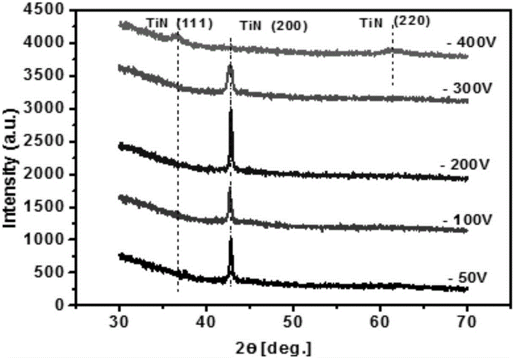
The invention provides a preparation method for a composite coating of a cutter. The preparation method for the composite coating of the cutter specifically comprises the steps that (A) the cleaned cutter is clamped on a workpiece rack of a high-power pulsed magnetron sputtering instrument, after vacuumizing, an electric heater is started, and then the electric heater is adjusted; (B) inertia gas is fed into a cavity of the high-power pulsed magnetron sputtering instrument, a bias power supply is started, and then glow cleaning is conducted on the cutter; (C) after glow cleaning is ended, the vacuum degree of the cavity of the high-power pulsed magnetron sputtering instrument is adjusted, and a titanium target is started for depositing a Ti layer; and (D) after bombarding is completed, a nitrogen flowmeter valve is opened, a TiN layer and a TiSiN layer are deposited, and the coating of the cutter is obtained after cooling. According to the preparation method for the composite coating of the cutter, the TiSiN nanometer composite coating is prepared through a high-power pulsed magnetron sputtering technology, and the preparation technology of the TiSiN-based coating of the cutter is stable, reliable and high in repeatability and has important application value for high-speed machining of materials difficult to machine, the improvement of the performance of various mechanical part products and the development of the equipment manufacturing industry.

Description

Technical field [0001] The invention relates to the field of tool coating preparation, in particular to a method for preparing a tool composite coating using high-power pulse magnetron sputtering technology. Background technique [0002] As a key tool for CNC and abrasive machining technology, its performance has a decisive influence on the efficiency, accuracy and surface quality of cutting. Coated tools use vapor deposition method to coat a few microns of high hardness, high wear resistance, refractory metal or non-metal compound coating on the surface of high-strength cemented carbide or high-speed steel tool substrate. Coated tools have the characteristics of high surface hardness, good wear resistance, stable chemical properties, heat resistance and oxidation resistance and low friction coefficient. MeSiN nanocomposite coatings add a certain amount of Si element to the traditional single-phase coatings such as TiN or CrN to cause thermodynamic amplitude modulation decomposi...

Claims


Application Information

Patent Timeline
IPC IPC(8): C23C14/35C23C14/16C23C14/06C23C14/02
CPCC23C14/0036C23C14/022C23C14/0641C23C14/165C23C14/3485C23C14/352
Inventor 王启民邹长伟丁继成郑军
Owner GUANGDONG UNIV OF TECH
Learn More