Device and method for cleaning extreme ultraviolet optical element surface contamination

A technology for optical components and cleaning devices, applied in cleaning methods and utensils, chemical instruments and methods, cleaning flexible objects, etc., can solve the problems of affecting the service life, increasing the temperature of optical components, and cleaning without help, etc., to improve long-term use Longevity, reduction of gradual damage, and effect of ensuring safety

Active Publication Date: 2018-10-23
CHANGCHUN INST OF OPTICS FINE MECHANICS & PHYSICS CHINESE ACAD OF SCI
View PDF5 Cites 0 Cited by
  • Summary
  • Abstract
  • Description
  • Claims
  • Application Information

AI Technical Summary

Problems solved by technology

[0009] However, from the actual situation currently used, there are still many deficiencies in the UV light irradiation cleaning method.
First of all, this method contains strong oxidizing oxygen atoms, which can easily oxidize the surface layer of EUVL optical components. Even the relatively oxidation-resistant Ru protective layer also has the risk of being oxidized.
Secondly, due to the fact that different EUVL optical components have different contamination conditions on the sample surface, there are many actual factors that affect the cleaning and removal rate of carbon contamination on the surface of optical components, which makes it difficult to better grasp the appropriate cleaning in actual use. processing time, which can easily lead to under-cleaning or over-cleaning
Third, although the power of the UV light generating device adopted in the prior art is higher, the spectral components it produces are also relatively complex. In addition to useful ultraviolet light, it also includes a large number of visible and near-infrared spectra. Cleaning does not help, but will be absorbed by the EUVL optical components, which will increase the temperature of the EUVL optical components, which will generate stress inside the EUVL optical components, which may cause damage to the EUVL optical components or affect their service life

Method used


Image

  • Device and method for cleaning extreme ultraviolet optical element surface contamination

Examples


Embodiment Construction

[0040] In order to make the object, technical solution and advantages of the present invention clearer, the present invention will be further described in detail below in conjunction with the accompanying drawings and specific embodiments. It should be understood that the specific embodiments described here are only used to explain the present invention, but not to limit the present invention.

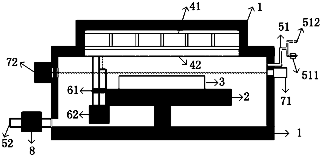
[0041] first reference figure 1 A device for cleaning the surface of an EUV optical element according to an embodiment of the present invention is shown. The cleaning device includes a cleaning chamber 1; an air inlet 51 and an air outlet 52 arranged on both sides of the cleaning chamber 1; a sample support adjustment table 2 arranged in the cleaning chamber 1, an ultraviolet light generating device, a CO 2 Concentration monitoring device, O 3 Concentration monitoring device; working gas control device, control circuit and control terminal.

[0042] Wherein, the sample support adjus...


PUM


Abstract

The invention relates to the technical field of extreme ultraviolet lithography, and specifically discloses an extreme ultraviolet optical element surface cleaning device and a cleaning method. The extreme ultraviolet optical element surface contamination cleaning device of the present invention includes a cleaning chamber; air inlets and gas outlets arranged on both sides of the cleaning chamber; a sample support adjustment table, an ultraviolet light generating device, and a CO2 concentration monitoring device arranged in the cleaning chamber device, O3 concentration monitoring device; also includes working gas control device, control circuit and control terminal. The cleaning device and cleaning method of the present invention can effectively realize the thorough cleaning of the surface contamination of the extreme ultraviolet optical element, prevent the oxidation of the surface of the extreme ultraviolet optical element at the same time, improve the potential long-term service life of the extreme ultraviolet optical element; and can ensure the safety of exhaust gas, Reduce the impact of the cleaning process on the laboratory environment and the safety and health of experimenters.

Description

technical field [0001] The invention relates to the technical field of integrated circuit manufacturing, in particular to a device and method for cleaning surface contamination of extreme ultraviolet optical elements. Background technique [0002] The extreme ultraviolet (EUVL) lithography technology with a wavelength of 13.5nm or 6.xnm is one of the main technologies to realize the manufacture of extremely large-scale integrated circuits with a node below 10nm in the future, and it plays a very important role in supporting the development of future information technology. Due to the extremely short wavelength, the EUV photon energy is very high, and it must be transmitted and used in a vacuum environment. Therefore, the optical components used in the EUVL lithography system often face various problems during preparation, storage, transportation and exposure. Deposition of particulate matter, carbon and organic contamination layers. Surface contamination of these optical co...

Claims


Application Information

Patent Timeline
Patent Type & Authority Patents(China)
IPC IPC(8): B08B11/00B08B7/00B08B13/00
CPCB08B7/0057B08B11/00B08B13/00
Inventor 邓文渊金春水姚舜喻波靳京城
Owner CHANGCHUN INST OF OPTICS FINE MECHANICS & PHYSICS CHINESE ACAD OF SCI
Why Eureka
Try Eureka