Polymer micro-fluidic chip and preparation method thereof
A microfluidic chip, polymer technology, applied in microstructure technology, microstructure devices, manufacturing microstructure devices, etc., can solve the problem of difficult to control the uniformity and continuity of the metal layer, affect the device effect, and difficult to realize microfluidic control. Accurate detection and other problems, to achieve the effect of large market application potential, easy mass production, and efficient preparation
- Summary
- Abstract
- Description
- Claims
- Application Information
AI Technical Summary
Problems solved by technology
Method used
Image
Examples
preparation example Construction
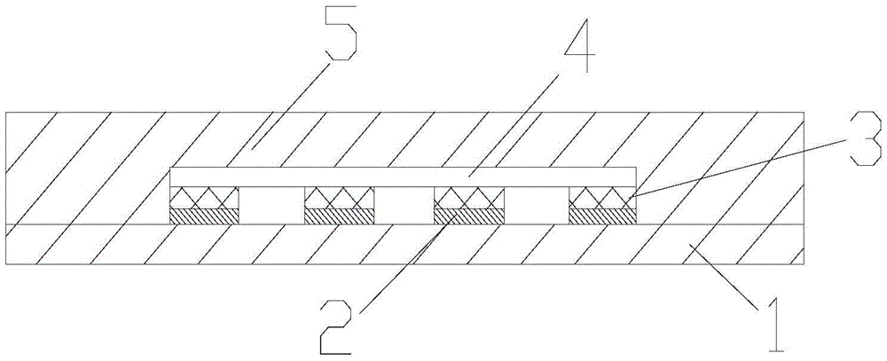
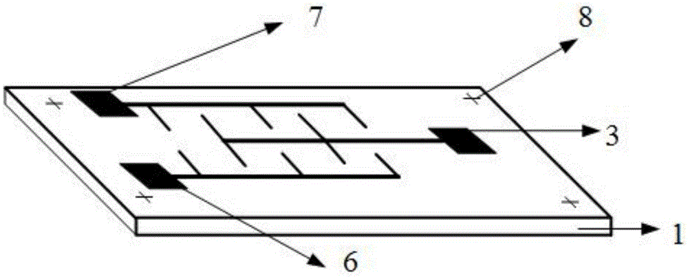
[0024] One aspect of the embodiments of the present invention provides a method for preparing a polymer microfluidic chip, which includes: using UV-LIGA technology to prepare a microfluidic channel mold, and then performing micro-injection molding or spin coating and peeling. The preparation of the microfluidic channel forms the microfluidic matrix, and finally connects the microfluidic matrix with the electrode matrix with electrodes by means of bonding or hot pressing to form a microfluidic detection chip.
[0025] In some embodiments, the preparation method of the polymer microfluidic chip may include:
[0026] providing a first polymer substrate comprising an electrode protruding from a first surface of the first polymer substrate;
[0027] Using UV-LIGA technology to prepare a micro-channel mold, and then using the micro-channel mold to prepare a second polymer matrix containing micro-channels by micro-injection molding, the micro-channels are recessed in the first a sec...
Embodiment 1
[0061] The microfluidic chip preparation process of embodiment 1 PDMS (polydimethylsiloxane) material comprises the following steps:
[0062] 1) Mix the PDMS material evenly, fully stir it with a mechanical stirrer, and then use a vacuum oven to pump air;
[0063] 2) On the glass substrate, spin-coat the treated PDMS material with a spin-coating device;
[0064] 3) Curing the PDMS spin-coated on the glass substrate at 80-200°C;
[0065] 4) Then sputtering a metal Ti layer 1 with a thickness of 20-50 nm on the substrate as a connecting layer;
[0066] 5) On the sputtered metal Ti layer, a layer of 100-200nm metal Au is sputtered;
[0067] 6) On the Au layer, throw a layer of glue with a thickness of about 2um, and perform pre-baking;
[0068] 7) Expose and develop the photoresist on the gold layer to pattern the Au test electrode
[0069] 8) Carry out glue rejection and photolithography to expose the counter electrode area;
[0070] 9) Sputtering 100-200nm metal Pt to achi...
Embodiment 2
[0084] The microfluidic chip preparation process of embodiment 2PMMA (polymethyl methacrylate) material comprises the following steps:
[0085] 1) Use high-transparency PMMA as the substrate, wash with acetone, ethanol, and deionized water, then blow dry with nitrogen, and place in an ultra-clean environment;
[0086] 2) Then sputter a metal Ti layer with a thickness of about 20-50 nm on the substrate as a connection layer;
[0087] 3) On the sputtered metal Ti layer, a metal Au film with a thickness of about 100-200 nm is sputtered;
[0088] 4) On the sputtered Au film, use the process steps of spin coating, exposure, and development to pattern the gold electrode;
[0089] 5) Then utilize the wet etching solution to etch out the gold electrode pattern;
[0090] 6) Utilize wet etching solution to etch excess titanium metal patterns;
[0091] 7) Carry out glue rejection and photolithography to expose the counter electrode area;
[0092] 8) Sputter metal Pt with a thickness ...
PUM
| Property | Measurement | Unit |
|---|---|---|
| Thickness | aaaaa | aaaaa |
| Thickness | aaaaa | aaaaa |
| Thickness | aaaaa | aaaaa |
Abstract
Description
Claims
Application Information
 - Generate Ideas
- Intellectual Property
- Life Sciences
- Materials
- Tech Scout
- Unparalleled Data Quality
- Higher Quality Content
- 60% Fewer Hallucinations
Browse by: Latest US Patents, China's latest patents, Technical Efficacy Thesaurus, Application Domain, Technology Topic, Popular Technical Reports.
© 2025 PatSnap. All rights reserved.Legal|Privacy policy|Modern Slavery Act Transparency Statement|Sitemap|About US| Contact US: help@patsnap.com


