
Coal-fired power generation system deeply integrated with calcium-based absorbent sequential desulfurization and decarbonization system

A calcium-based absorbent and power generation system technology, which is applied in steam generation, machines/engines, and energy industries, can solve the problems of high energy consumption for compression, high energy consumption for air separation, and high energy consumption for calcination, so as to reduce energy consumption, Effect of improving thermal efficiency and reducing oxygen consumption

Active Publication Date: 2017-10-10
NORTH CHINA ELECTRIC POWER UNIV (BAODING)
View PDF8 Cites 0 Cited by
  • Summary
  • Abstract
  • Description
  • Claims
  • Application Information

AI Technical Summary

Problems solved by technology

Calcium-based Absorbent Cyclic Calcination / Carbonation for CO Capture 2 It is one of the most promising technologies, but the disadvantages of this method are high energy consumption for calcination, high energy consumption for air separation, and CO 2 Compression consumes a lot of energy, which leads to a significant drop in the thermal efficiency of the entire system with this method

Method used


Image

  • Coal-fired power generation system deeply integrated with calcium-based absorbent sequential desulfurization and decarbonization system
  • Coal-fired power generation system deeply integrated with calcium-based absorbent sequential desulfurization and decarbonization system
  • Coal-fired power generation system deeply integrated with calcium-based absorbent sequential desulfurization and decarbonization system

Examples


Embodiment Construction

[0028] The present invention will be further described below in conjunction with the accompanying drawings and specific embodiments. It should be emphasized that the following description is only exemplary and not intended to limit the scope of the invention and its application.

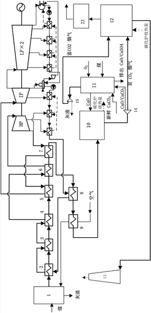
[0029] Such as figure 1 As shown in the flow chart of the benchmark system, the flue gas of the power plant passes through the water wall 2, the partition superheater 3, the rear panel superheater 4, the high temperature reheater 5, the final superheater 6, the low temperature reheater 7, and the economizer 8 1. The air preheater 9 enters the carbonization furnace 10 for desulfurization and decarbonization after heat exchange. The operating temperature of the carbonization furnace 10 is 650°C. The exported logistics is divided into two streams, and the CO-depleted stream after desulfurization and decarbonization 2 The flue gas is discharged into the atmosphere after being recovered by the waste hea...


PUM


Abstract

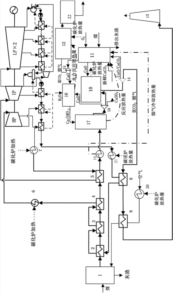
The invention relates to a coal-fired power generation system deeply and integrally provided with a system for desulfurizing and decarburizing a calcium-based sorbent in sequence. A heat source of a finishing superheater and a heat source of a low-temperature reheater are replaced with heat discharged from a carbide furnace, high-temperature smoke of an outlet of a high-temperature reheater outlet of an original standard system is cooled through a first heat exchanger and then directly enters a vulcanization reactor to be desulfurized, and CaSO4 is discharged; the heat discharged due to heat exchange of the first heat exchanger and heat discharged from a reaction in a sulfuration reactor are used for heating a calcinator; and remaining CaO after desulfurizing is conducted and inactivated CaO discharged from the calcinator are recovered and enter a hydration reactor to be subjected to hydrate activation and then enter a desulfurizing circulation, the desulfurized smoke enters the carbide furnace to be decarburized, waste heat of the smoke with lean CO2 of an outlet of the carbide furnace is recovered through an economizer and an air preheater, partial heat discharged from the carbide furnace is provided to heat the economizer and the air preheater to maintain the design parameters of an original power plant unchanged, the heat discharged from the hydration reactor and remaining heat after the heat load is replaced with the carbide furnace are recovered by a waste heat boiler module to be used for generating steam for acting.

Description

technical field [0001] The invention belongs to the calcium-based absorbent cycle calcination / carbonation (CCCR) method for carbon capture CO 2 The technical field, in particular, relates to a coal-fired power generation system deeply integrated with a calcium-based absorbent sequential desulfurization and decarbonization system. Background technique [0002] CO in flue gas from thermal power plants 2 Exacerbating the global greenhouse effect, and currently for existing thermal power plants, post-combustion capture is an effective way to capture CO 2 The way. Calcium-based Absorbent Cyclic Calcination / Carbonation for CO Capture 2 It is one of the most promising technologies, but the disadvantages of this method are high energy consumption for calcination, high energy consumption for air separation, and CO 2 Compression consumes a lot of energy, which leads to a significant drop in the thermal efficiency of the entire system when this method is adopted. Contents of the ...

Claims


Application Information

Patent Timeline
Patent Type & Authority Patents(China)
IPC IPC(8): F23J7/00F23J15/02F22D11/00F01D15/10
CPCF01D15/10F22D11/00F23J7/00F23J15/02Y02P80/15
Inventor 段立强高超乐龙冯涛
Owner NORTH CHINA ELECTRIC POWER UNIV (BAODING)
Learn More