ion generator
A technology of ion generating device and high-voltage generator, which is applied in the direction of electrical components, etc., can solve problems such as difficulty in ensuring stable operation, inability to resonate, and many variable parameters, so as to eliminate the generation of ozone and static electricity and increase the discharge voltage.
- Summary
- Abstract
- Description
- Claims
- Application Information
AI Technical Summary
Problems solved by technology
Method used
Image
Examples
Embodiment 1
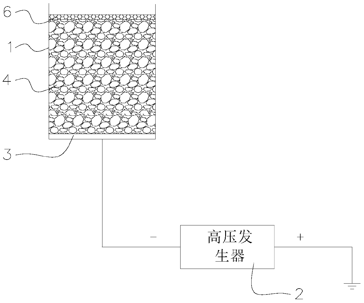
[0027] The ion generating device of the present embodiment, see figure 1 , including an insulating case 1 and an electrode 3 arranged in the insulating case, the electrode 3 is electrically connected to the high voltage output end of the high voltage generator 2; the top of the insulating case 1 is open, the electrode 3 is arranged at the bottom of the insulating case 1, and the insulating The casing 1 is filled with an inert insulating material 4 (ie a uniform inert material) with micropores, wherein the diameters of the micropores are basically the same. In this embodiment, the high voltage generator 2 adopts a negative ion generator, and the voltage of its negative high voltage output terminal is: -9KV. Of course, according to different occasions and different requirements, the high-voltage generator 2 of this embodiment can also use a positive ion generator or a plasma generator.
[0028] In this embodiment, the inert insulating material 4 with micropores is composed of m...
Embodiment 2
[0035] The ion generating device of this embodiment is basically the same as that of Embodiment 1, as figure 1 As shown, the different changes from Example 1 are: 1) The micropore diameter of the membrane material 4 is 0.001mm. 2) The aqueous solution rich in hydrogen ions is adsorbed in the porous sponge to form an aqueous liquid layer, which can generate more hydrogen-rich ions; of course, it can also be filled with other aqueous solutions, such as medicinal liquid, etc., if a suitable medicinal liquid is used, it can also play a role The effect of curing and preventing diseases. 3) The voltage of the negative high voltage output terminal of the high voltage generator 2 is: -10KV.
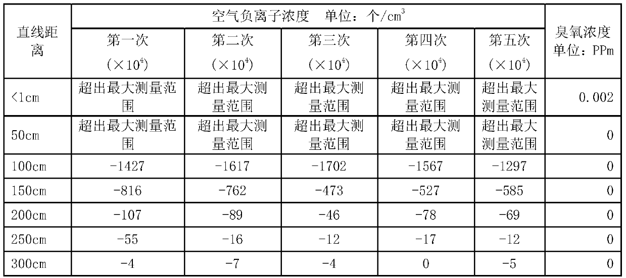
[0036] The test of ion concentration and ozone concentration in the test air is carried out at different distances from the top opening of the insulating housing 1 respectively, and the results are shown in Table 2:
[0037] Table 2
[0038]
[0039]
Embodiment 3
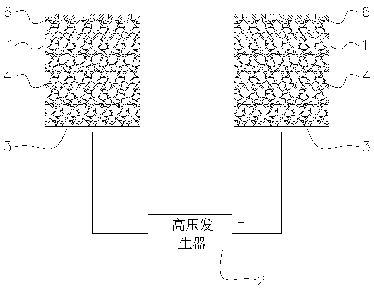
[0041] The ion generating device of this embodiment is an improvement on the basis of Embodiment 1, such as figure 2 As shown, the improvement compared with the first embodiment is: the negative high voltage output terminal and the positive high voltage output terminal of the high voltage generator 2 are respectively electrically connected to the electrodes 3 on the inner bottom surface of the two insulating shells 1 . The insulating housing 1 is densely filled with fibrous material 4 (that is, an inert insulating material with micropores), and the diameter of the micropores is 0.4 mm. The top of the fiber material 4 in this embodiment is provided with a perforated baffle 6 , and tap water is provided inside the perforated baffle 6 to form a liquid layer of an aqueous solution (not shown in the figure). The size of the insulating shell of the high voltage generator 2: 20×25×10 mm, the voltage range of the high voltage output terminal of the high voltage generator 2: plus or m...
PUM
 Abstract
Description
Claims
Application Information
 - R&D
- Intellectual Property
- Life Sciences
- Materials
- Tech Scout
- Unparalleled Data Quality
- Higher Quality Content
- 60% Fewer Hallucinations
Browse by: Latest US Patents, China's latest patents, Technical Efficacy Thesaurus, Application Domain, Technology Topic, Popular Technical Reports.
© 2025 PatSnap. All rights reserved.Legal|Privacy policy|Modern Slavery Act Transparency Statement|Sitemap|About US| Contact US: help@patsnap.com


