Preparation method of heat-shrinkage-resistant power battery separator
A technology for power batteries and separators, applied in the field of preparation of power battery separators, can solve the problems of many coating processes and complex comprehensive performance control processes, and achieves fast deposition rate, simple manufacturing method and production equipment, good adhesion performance and durability. The effect of high temperature performance
- Summary
- Abstract
- Description
- Claims
- Application Information
AI Technical Summary
Problems solved by technology
Method used
Image


Examples
Embodiment 1
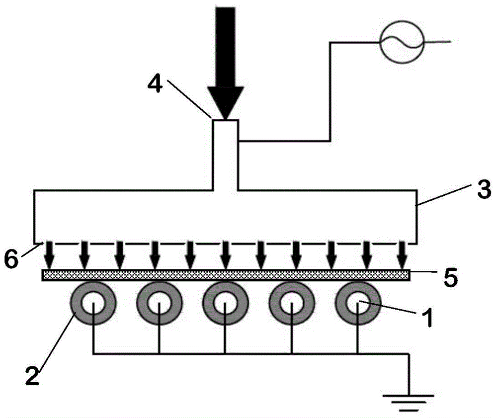
[0059] The structure of the plasma reactor using the combination of comb electrode and nozzle electrode is as follows: figure 1 As shown, the reactor includes a comb electrode barrier dielectric tube 2 and a nozzle electrode 3, and the discharge gap is 0.50mm. The blocking medium of the comb-shaped electrodes is quartz, and the distance between the comb-shaped electrodes is 1.00mm. The nozzle electrode 3 is a stainless steel electrode. The substrate is located between electrodes. The frequency of the AC power supply is 10KHz. A high-strength high-modulus polyethylene film 5 with a thickness of 18.00 μm is placed between the barrier medium tube 2 and the shower head electrode 3 and above the ground electrode.
[0060] Under normal temperature and pressure, the discharge gas argon with a flow rate of 0.1slm, the reaction gas oxygen with a flow ratio of 1 / 1000 to the discharge gas, and the carrier gas with a flow ratio of 1 / 500 to the discharge gas (the same as the discharge ...
Embodiment 2
[0063] A plasma reactor structure in which comb-shaped electrodes are cross-combined with comb-shaped electrodes is adopted. The comb-shaped electrodes are covered by a barrier dielectric tube, the discharge gap between the upper and lower comb-shaped electrodes is 2 mm, and the distance between the comb-shaped electrodes is 1 mm. A polyethylene diaphragm 5 with a thickness of 30 μm is placed between the upper and lower barrier medium tubes, above the ground electrode.
[0064] Under normal temperature and pressure, the discharge gas helium with a flow rate of 2slm, the reaction gas oxygen and carbon dioxide gas with a flow rate of 1 / 500 to the discharge gas (each accounting for 1 / 2 ratio), and the carrier gas with a flow rate of 1 / 25 to the discharge gas (same as discharge gas, controlled by different flowmeters) TiCl 4 The loading is carried out through the air inlet 4, and enters the dielectric barrier discharge plasma reactor through the air outlet 6. The frequency of the ...
Embodiment 3
[0067] A plasma reactor structure in which a comb-shaped electrode is combined with a wire-mesh electrode is adopted. The comb-shaped electrode is covered by a barrier medium tube, and the discharge gap between the comb-shaped electrode and the wire-mesh electrode is 5 mm. The spacing is 2mm. A polyethylene diaphragm 5 with a thickness of 15 μm was placed between the comb-shaped electrode and the wire-mesh electrode, above the ground electrode.
[0068] Under normal temperature and pressure, discharge gas argon with a flow rate of 5slm, oxygen with a flow ratio of 1 / 1 to the discharge gas, and carrier gas with a flow ratio of 1 / 10 to the discharge gas (same as the discharge gas, controlled by a different flowmeter) Carry out the trimethylaluminum through the air inlet 4, enter the dielectric barrier discharge plasma reactor through the air outlet 6, set the AC frequency to 150KHz, and the voltage to 30000V, and discharge the mixed gas through a high-voltage AC power supply Pl...
PUM
| Property | Measurement | Unit |
|---|---|---|
| thickness | aaaaa | aaaaa |
Abstract
Description
Claims
Application Information
 - R&D
- Intellectual Property
- Life Sciences
- Materials
- Tech Scout
- Unparalleled Data Quality
- Higher Quality Content
- 60% Fewer Hallucinations
Browse by: Latest US Patents, China's latest patents, Technical Efficacy Thesaurus, Application Domain, Technology Topic, Popular Technical Reports.
© 2025 PatSnap. All rights reserved.Legal|Privacy policy|Modern Slavery Act Transparency Statement|Sitemap|About US| Contact US: help@patsnap.com