Electric melting forming method of metal component

A metal component and electrofusion technology, which is applied in the field of metal component electrofusion forming, achieves the effects of no macro segregation, improved mechanical properties, and improved plasticity

Active Publication Date: 2015-04-22
NANFANG ADDITIVE MFG TECH
View PDF5 Cites 24 Cited by
  • Summary
  • Abstract
  • Description
  • Claims
  • Application Information

AI Technical Summary

Problems solved by technology

[0004] 3D printing, due to its high degree of manufacturing flexibility, short forming cycle, and fast processing speed, has been widely used in the forming of product module models, such as the use of low-melting point materials such as paraffin and resin to form workpiece models. It is also used in specific industries such as Significant breakthroughs and applications have been made in the manufacture of aerospace titanium alloy metal components, but there are still many difficulties to overcome in order to fully enter the manufacturing industry, especially the heavy equipment manufacturing industry

Method used


Image

  • Electric melting forming method of metal component
  • Electric melting forming method of metal component
  • Electric melting forming method of metal component

Examples


Embodiment 1

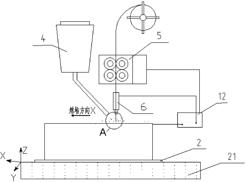
[0039] Horizontal production of rotary cylinder. This example describes the process of making a cylinder by horizontal electrofusion forming. The material is ordinary low-carbon steel. The equipment used includes:

[0040] (1) Rotary support table; (2) Electrofusion power supply; (3) Electrofusion head; (4) Automatic wire feeding device; (5) Automatic auxiliary material conveying and auxiliary material automatic recovery device; (6) Heating device; (7) Cooling device; (8) substrate; (9) control device (computer).

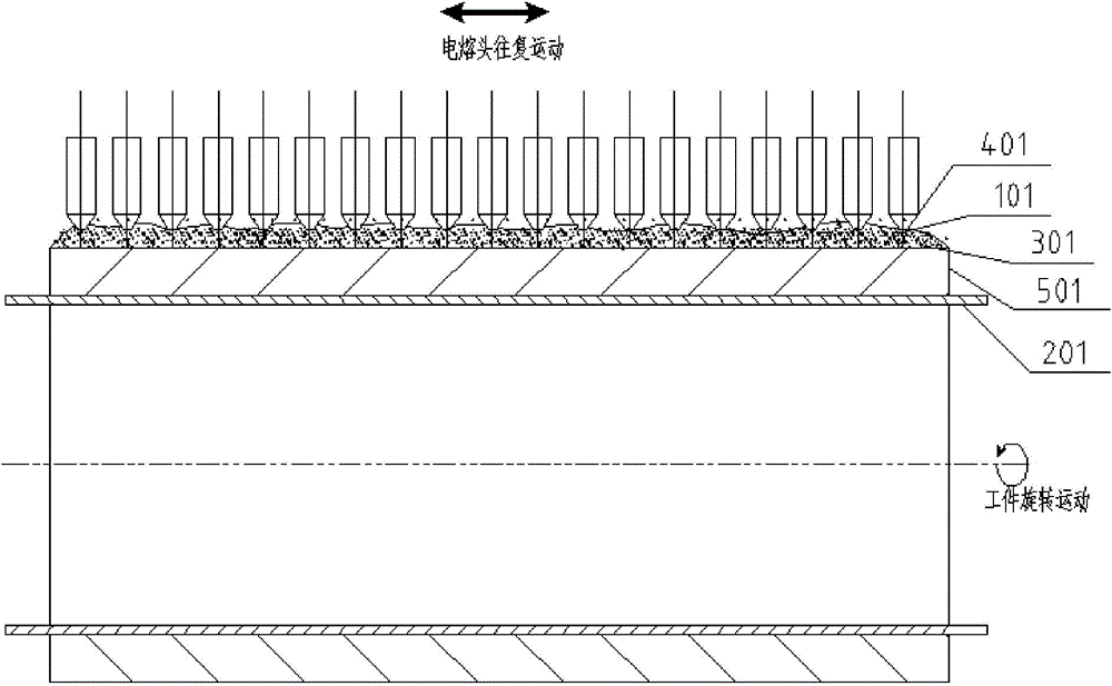
[0041] figure 2 It is a schematic explanatory diagram for showing the electrofusion forming method of this embodiment, and devices such as a power supply and an automatic wire feeding device are omitted in the figure. Such as figure 2 As shown, select common low-carbon steel raw material wire material 101, diameter 4mm, 19 electrofusion heads 401, the electrofusion power supply is a DC power supply, the electrofusion head 401 is connected to the negative pole o...

Embodiment 2

[0053] Vertical production of rotary body. Adopt a kind of metal member electrofusion forming method vertical growth to make a cylindrical metal member, the equipment used in this embodiment includes,

[0054] (1) Rotary support table; (2) Electrofusion power supply; (3) Electrofusion head; (4) Automatic wire feeding device; (5) Automatic auxiliary material conveying and auxiliary material automatic recovery device; (6) Blocking auxiliary material device; (7) ) heating device; (8) cooling device; (9) substrate; (10) control device.

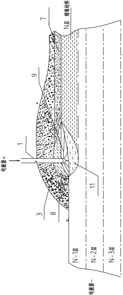
[0055] image 3 It is a schematic explanatory diagram showing the electrofusion forming method of this embodiment, and devices such as a rotary support table and a power supply are omitted in the figure. Such as image 3 As shown, choose ordinary low-carbon steel raw material wire, diameter 5mm, special auxiliary materials, an electric fusion head 602, the electric fusion power supply is a DC power supply, the electric fusion head is connected ...

Embodiment 3

[0066] Production of special-shaped workpieces. H08A ordinary low-carbon steel wire is selected, and a metal member electrofusion forming method is used to vertically grow the head metal member. The equipment used in this embodiment includes:

[0067] (1) Rotary support table; (2) Electrofusion power supply; (3) Electrofusion head; (4) Automatic wire feeding device; (5) Automatic auxiliary material conveying and auxiliary material automatic recovery device; (6) Blocking auxiliary material device; (7) ) heating device; (8) cooling device; (9) substrate; (10) control device.

[0068] Figure 4 It is a schematic explanatory diagram showing the electrofusion forming method of this embodiment, and the equipment is omitted in the figure for simplification. The selected parameters are: diameter of wire rod is 5mm, auxiliary material is 30% Fe powder added to standard melting flux SJ101, setting electric melting current is 900A, electric melting voltage is 40V, electric fusion head ...


PUM

PropertyMeasurementUnit
diameteraaaaaaaaaa
thicknessaaaaaaaaaa
lengthaaaaaaaaaa

Abstract

The invention provides an electric melting forming method of a metal component, which has the advantages of high efficiency, low cost and excellent mechanical performance. In the method, an electric melting head and a substrate are connected to two poles of a power supply; a raw metal wire is conveyed to the surface of the substrate by a conveying mechanism and the electric melting head in forming; under the stacking protection of granular accessories, an electric arc is generated between the raw metal wire and the substrate; a molten part is overlaid on the accessories to form a molten slag pool; current flows through the raw metal wire and the molten slag pool to form resistance heat and electroslag heat; the raw metal wire is molten under the effect of three thermal compound high-energy heat sources of electric arc heat, the resistance heat and the electroslag heatto form a local molten pool on the surface of the base material; the raw metal wire and the accessories are continuously conveyed; the relative movement of the electric melting head and the substrate is controlled by a computer according to hierarchical slicing data of the formed component to realize quick cooling and layer-by-layer condensation and accumulation of the molten pool on the substrate; and finally, the metal component with the needed shape and size is formed through layer-by-layer accumulation.

Description

technical field [0001] The invention relates to an electric melting forming method of a metal component. Background technique [0002] At present, modern heavy industrial equipment such as nuclear power, thermal power, petrochemical, metallurgy, and shipbuilding is rapidly developing towards large-scale, complex, high-performance parameters, high reliability, and long-life service under extreme conditions. The required low-alloy high-strength steel The size of key metal components such as heat-resistant alloys and heat-resistant alloys is also increasing, and the quality requirements are getting higher and higher. Its manufacturing method mainly adopts hundreds of tons of large-scale steel ingot smelting, casting and forging and pressing of heavy forging industrial equipment such as 10,000-ton hydraulic press, supplemented by final machining. This method can basically meet the technical quality requirements, but the manufacturing process is numerous, the production cycle is...

Claims


Application Information

Patent Timeline
Patent Type & Authority Applications(China)
IPC IPC(8): B23K28/02
CPCB23K28/02B22F10/66B22F10/25B22F12/20B22F12/10B22F12/37B22F12/55B22F2999/00B22F10/73B22F12/53B22F2202/06B23K9/04B23K9/18B23K25/005B33Y10/00B33Y30/00Y02P10/25B29C64/282B29C64/153B29C64/295B05C19/04B28B1/001B29C70/82H05K3/103
Inventor 不公告发明人
Owner NANFANG ADDITIVE MFG TECH
Why Eureka
Try Eureka