
Smoke purification technology implemented based on adsorbent pretreatment

A flue gas purification process and absorbent technology, applied in chemical instruments and methods, dispersed particle separation, separation methods, etc., can solve the problems of unobvious industrial application, long process flow, poor technical economy, etc., and improve desulfurization and denitrification efficiency , Improve processing efficiency, high crushing efficiency

Active Publication Date: 2015-02-18
CHENGDU HUAXITANG INVESTMENT
View PDF8 Cites 5 Cited by
  • Summary
  • Abstract
  • Description
  • Claims
  • Application Information

AI Technical Summary

Problems solved by technology

[0004] At present, the flue gas desulfurization and denitrification technology widely used in the world is to use the above-mentioned traditional flue gas desulfurization technology combined with SCR denitrification technology to achieve the purpose of desulfurization and denitrification. Although this technology can remove more than 90% of SO 2 and more than 80% NOx, but this method is actually still a combination of separate desulfurization and denitrification technologies, and has the disadvantages of the above-mentioned desulfurization and denitrification technologies, and cannot get rid of the long process flow, large investment, and high operating costs. , poor technical economy, easy to cause secondary pollution and other problems
From the existing patent documents CN102489129A (industrial flue gas purification, desulfurization and denitrification integrated device and its working method, 2012.06.13), CN203108424U (a flue gas treatment device for simultaneous desulfurization and denitrification, 2013.08.07), we know that combined desulfurization Denitrification technology has gradually become the development direction of flue gas treatment, but this kind of integrated flue gas desulfurization and denitrification technology is often not mature enough. SO in Dao gas 2 or NO X For rough purification, the methods used include ozone injection, cooling, absorbents, etc., and patent documents CN102363095A (flue gas dry desulfurization process and flue gas dry desulfurization system, 2012.02.29), CN103990375A (a semi Dry sintering flue gas integrated purification method, 2014.08.20), etc., in the actual use process, its treatment efficiency is not obvious from the whole desulfurization (denitrification) process, so their industrial application is not obvious. not obvious

Method used


Image

  • Smoke purification technology implemented based on adsorbent pretreatment
  • Smoke purification technology implemented based on adsorbent pretreatment
  • Smoke purification technology implemented based on adsorbent pretreatment

Examples


Embodiment 1

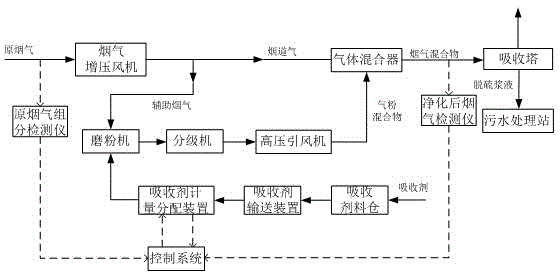
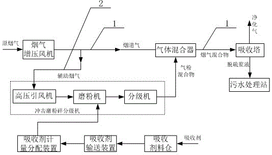
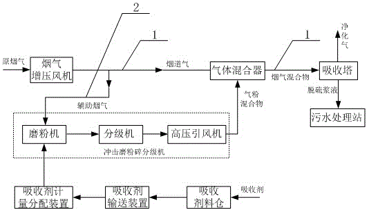
[0037] In the traditional flue gas purification method, the rough purification process of the raw flue gas by the absorbent usually includes: metering the absorbent, and then sending it into the pulverizer system for pulverization, and then sending the pulverized absorbent particles through a dry powder injector. The main flue 1 mixes and reacts with the raw flue gas. During this process, the purification efficiency of the absorbent to the raw flue gas is usually about 50%, and the desulfurization efficiency is low. Therefore, in order to improve the working efficiency of the absorbent, this The invention proposes a flue gas purification process based on absorbent pretreatment. The flue gas purification process includes sending the original flue gas in the main flue into SO through the flue gas system. 2 Absorption system, in order to overcome the above defects, the present invention improves the flue gas system. In the present invention, the flue gas system is mainly composed ...

Embodiment 2

[0039] The difference between this embodiment and Embodiment 1 is that in this embodiment, after the original flue gas is split, the volume ratio of the auxiliary flue gas passing through the auxiliary flue 2 and the flue gas passing through the main flue 1 is 9: 1.

[0040] In the actual application process of this embodiment, the original flue gas is sent into the main flue 1 through the flue gas booster fan, and a part of the original flue gas enters the auxiliary flue 2 through the entrance of the auxiliary flue 2, which is called auxiliary flue gas. A part of the original flue gas remains in the main flue 1, which is called flue gas. The auxiliary flue gas drives the absorbent and enters the impact mill crushing classifier together. The absorbent is pretreated in the impact mill crushing classifier and combined with the auxiliary flue gas. reaction, the obtained gas-powder mixture is sent to the main flue 1 through the outlet of the flue, and then mixed with the flue gas ...

Embodiment 3

[0042] The difference between this embodiment and Embodiment 2 is that in this embodiment, the impact mill pulverizing classifier is mainly composed of a pulverizer, a classifier and a high-pressure induced draft fan, and the absorbent and auxiliary flue gas are sent into the mill with the high-pressure induced draft fan. The absorbent is pulverized and then sent to the classifier with the auxiliary flue gas for screening. In the actual operation process, the gas-powder mixture can be selected by adjusting the speed of the classifier. Usually, the particle size of the absorbent in the gas-powder mixture It is controlled at 10-40um, that is, the absorbent with a particle size of ≤40um is mixed with auxiliary flue gas to obtain a gas-powder mixture, and the absorbent with a particle size>40um is returned to the mill for further pulverization.

[0043] Since the amount of absorbent introduced is related to the pollutant content in the original flue gas, it is necessary to monitor ...


PUM


Abstract

The invention discloses a smoke purification technology implemented based on adsorbent pretreatment. According to the smoke purification technology, raw smoke in a main flue is conveyed into a SO2 absorption system through a smoke system; the smoke system mainly comprises an auxiliary flue and the main flue which are communicated with each other; an impact pulverizing grading machine is arranged in the auxiliary flue; the raw smoke comprises auxiliary smoke passing through the auxiliary flue and flue gas passing through the main flue; an absorbent is conveyed into the impact pulverizing grading machine along with the auxiliary smoke, and an obtained gas-powder mixture enters the main flue and is subjected to mixing reaction with the flue gas; the obtained mixture is conveyed to the SO2 absorption system. The smoke purification technology is designed specially for rough purification of the flue gas, so that the desulfuration and denitration efficiency of the absorbent is greatly improved; the smoke purification technology has an extremely effect for promoting the treatment efficiency of a subsequent desulfuration and denitration technology.

Description

technical field [0001] The invention is a flue gas purification process realized based on absorbent pretreatment, specifically relates to the technical treatment of absorbent in the process of using a desulfurization and denitrification process to realize flue gas purification, and belongs to the field of flue gas purification. Background technique [0002] The continuous progress of petroleum and chemical industries has not only promoted economic development, but also caused pollution to the environment. At present, the global pollution problem has become increasingly serious, and has attracted widespread attention and attention from all over the world, especially coal-fired power plants. , coal-fired boilers, and waste incineration flue gas emissions, etc., have seriously polluted the atmosphere. We know that coal-fired flue gas contains a large amount of soot, carbon dioxide, SO 2 and NO X Among them, the carbon dioxide emitted by fuel combustion is the main substance th...

Claims


Application Information

Patent Timeline
Patent Type & Authority Applications(China)
IPC IPC(8): B01D53/83B01D53/75B01D53/60
Inventor 李东林罗仕林汪然陈洪会郎治
Owner CHENGDU HUAXITANG INVESTMENT
Learn More