
Device and method for use of impeller of laser 3D (three dimensional) -printing pump

A printing pump, 3D technology, applied in the direction of turbines, other manufacturing equipment/tools, engine components, etc., can solve the problems of different mechanical performance requirements of pump impellers, achieve resource saving, excellent surface performance, and reduce printing costs.

Active Publication Date: 2014-12-24
江苏大学扬州(江都)新能源汽车产业研究所
View PDF7 Cites 40 Cited by
  • Summary
  • Abstract
  • Description
  • Claims
  • Application Information

AI Technical Summary

Problems solved by technology

[0006] The purpose of the present invention is to provide an easy-to-implement and effective laser 3D printing device and method to print pump impellers in view of the problem that the 3D printing technology cannot well solve the problem that different parts of the pump impeller have different mechanical properties.

Method used


Image

  • Device and method for use of impeller of laser 3D (three dimensional) -printing pump
  • Device and method for use of impeller of laser 3D (three dimensional) -printing pump

Examples


Embodiment Construction

[0021] The present invention will be described in further detail below in conjunction with specific examples.

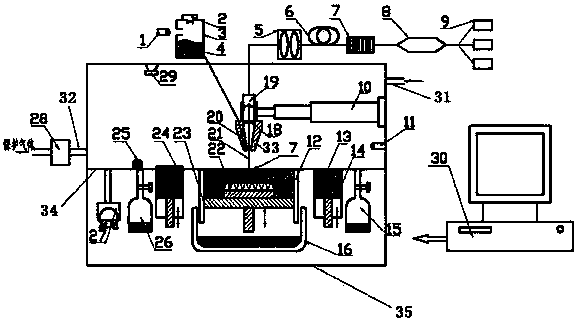
[0022] A device for laser 3D printing pump impellers, such as figure 1 As shown, it includes a laser head 19, a powder feeder 3, a powder spray head 33, a three-degree-of-freedom manipulator 10, a worktable 34, a vacuum pump 27 and a closed cavity 35, the laser head 19 is installed on the powder spray head 33, and the laser head 19 is sequentially connected with focusing collimator 5 , double-clad ytterbium-doped ion fiber 6 , fiber grating 7 , coupler 8 and multimode laser diode pumping source 9 . The powder feeder 3 is connected with the powder inlet hole 20 on the powder nozzle, the powder feeder 3 is provided with a powder feeding port 2, and the powder feeder 3 is connected with the argon gas source 1, which is used for the powder feeder 3 provides power, the powder nozzle 33 is controlled by the three-degree-of-freedom manipulator 10, and can move up and down,...


PUM

PropertyMeasurementUnit
Thicknessaaaaaaaaaa

Abstract

The invention discloses a device and a method for the use of an impeller of a laser 3D (three dimensional) -printing pump, and belongs to the field of 3D printing technology. The device comprises a laser system, a gas protection system, a preheating system, a powder feeding system, a powder paving system, a powder recycle system and a computer system. The manufacturing method mainly comprises the following steps that 1, a CAD solid model of the pump impeller is drawn, and the model is subjected to hierarchical slicing along the Z direction; 2, the slice in each layer is zoned into a zone I and a zone II according to the performance requirements of the pump impeller; 3, the zone I of each slice layer is subjected to low-speed sintering by using powder A, and the zone II is subjected to low-speed sintering by using powder B. The surface of a workpiece and the powder flow filed are subjected to the inert gas shielding in the process of printing. According to the device and the method for the use of the impeller of the laser 3D-printing pump, different requirements of different positions of the pump impeller on mechanical performance can be met, the printing quality and speed are also improved, and the manufacturing cost is reduced.

Description

technical field [0001] The invention relates to a method for laser 3D printing metal parts, in particular to a method for 3D laser printing impellers for pumps. Background technique [0002] 3D printing technology is based on the computer three-dimensional design model, through the software layered discrete and numerical control forming system, using laser beams, hot-melt nozzles, etc. to accumulate metal powder, ceramic powder, plastic, cell tissue and other special materials layer by layer Bonding, and finally overlaying and molding to create a solid product. [0003] SLS (Selective Laser Sintering) utilizes the principle that powder materials are sintered under laser irradiation, and is formed by computer-controlled layer-by-layer stacking. SLS technology also uses layered stacking molding, the difference is that it first lays a layer of powder material, preheats the material to close to the melting point, and then uses laser scanning on the layer section to raise the po...

Claims


Application Information

Patent Timeline
IPC IPC(8): B22F3/105B22F7/06B22F5/00
Inventor 任旭东周王凡袁寿其刘厚林卢加兴王勇王德顺左成亚吴坤
Owner 江苏大学扬州(江都)新能源汽车产业研究所
Learn More