Simulative microwave optical link amplitude and phase regulating and controlling device

A microwave optical link and control device technology, applied in electromagnetic wave transmission systems, electrical components, transmission systems, etc., can solve the problems of signal amplitude influence, amplitude and phase control are not independent, and cannot process broadband signals, etc., achieving great flexibility , Multiple adjustment methods, overcome the effect of limited signal bandwidth

Active Publication Date: 2014-07-02
THE 44TH INST OF CHINA ELECTRONICS TECH GROUP CORP
View PDF5 Cites 3 Cited by
  • Summary
  • Abstract
  • Description
  • Claims
  • Application Information

AI Technical Summary

Problems solved by technology

[0004] Since the formation of the beam network needs to perform weighted processing on the amplitude and phase of multiple signals, it is necessary to fine-tune the amplitude and phase of the optical-borne microwave signal in a single analog microwave optical link; in the prior art, the analog microwave optical When adjusting the amplitude and phase of the link, the following methods are generally used: first restore the microwave signal carried by light to an electrical signal, and then adjust the amplitude and phase of the electrical signal in the radio frequency domain. The phase shifter is used for regulation and control, wherein, the electric attenuator is used for regulating the amplitude of the electric signal, and the electric phase shifter is used for regulating the phase of the electric signal; While adjusting the phase, due to its own characteristic limitations, it will inevitably affect the signal amplitude, resulting in independent amplitude and phase regulation; secondly, with the increase of the frequency or bandwidth of the RF signal and the expansion of the link scale, Electric attenuators and electric phase shifters cannot handle broadband signals, and have great limitations in application

Method used


Image

  • Simulative microwave optical link amplitude and phase regulating and controlling device
  • Simulative microwave optical link amplitude and phase regulating and controlling device
  • Simulative microwave optical link amplitude and phase regulating and controlling device

Examples


Embodiment Construction

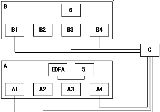
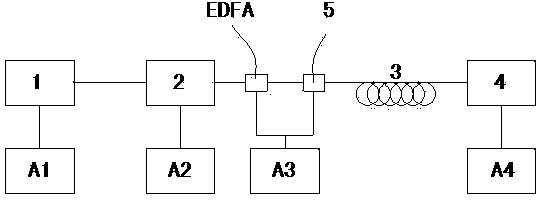
[0026] An analog microwave optical link amplitude and phase control device, including a single microwave optical transmission link, the microwave optical transmission link is formed by sequentially connecting a laser 1, an external modulator 2, a transmission fiber 3 and a photodetector 4; The innovation lies in: the analog microwave optical link amplitude and phase adjustment device is composed of an amplitude adjustment module A, a phase adjustment module B and a control module C;

[0027]The amplitude adjustment module A is composed of a laser power adjustment module A1, a modulator conversion efficiency adjustment module A2, an optical fiber gain adjustment module A3, a first detector bias adjustment module A4, an erbium-doped optical amplifier EDFA and an optical attenuator 5;

[0028] Wherein, the laser power adjustment module A1 is electrically connected to the laser 1 through the first control circuit, and the laser power adjustment module A1 can adjust the optical powe...


PUM


Abstract

A simulative microwave optical link amplitude and phase regulating and controlling device comprises a single microwave optical transmission link, and the microwave optical transmission link is formed by connecting a laser, an outer modulator, a transmission optical fiber and an optical detector in sequence. The simulative microwave optical link amplitude and phase regulating and controlling device is characterized in that the simulative microwave optical link amplitude and phase regulating and controlling device is composed of an amplitude regulating module, a phase regulating module and a control module, wherein the amplitude regulating module and the phase regulating module can independently regulate and control related parameters in an optical domain. The simulative microwave optical link amplitude and phase regulating and controlling device has the advantages that the regulation of the amplitude and the regulation of the phases of a simulative microwave optical link can be carried out independently, mutual interference can be avoided, regulating modes are various, regulation flexibility is large, and regulation accuracy is high; meanwhile, regulation and control measures are all completed in the optical domain, and the problem of limitation of signal bandwidths is solved.

Description

technical field [0001] The invention relates to an analog microwave optical link signal modulation technology, in particular to an analog microwave optical link amplitude and phase control device. Background technique [0002] In recent years, analog microwave photon transmission technology has attracted more and more attention from the industry due to its characteristics such as low transmission loss, large bandwidth, anti-electromagnetic interference, portability and flexibility. [0003] Such as figure 1 As shown in the figure, the structure shown in the figure is a typical externally modulated microwave optical transmission link. The optical transmission link is composed of four main parts: laser, external modulator, transmission fiber and optical detector. Among them, the laser is used to output as The light wave used by the optical carrier, the external modulator is used to load the radio frequency electrical signal on the optical carrier to form an optical microw...

Claims


Application Information

Patent Timeline
Patent Type & Authority Applications(China)
IPC IPC(8): H04B10/564H04B10/572
Inventor 瞿鹏飞孙力军
Owner THE 44TH INST OF CHINA ELECTRONICS TECH GROUP CORP
Why Eureka
Try Eureka