
Method for shaping continuous fiber reinforced thermoplastic resin and shaping equipment thereof

A thermoplastic resin and enhanced thermoplastic technology, applied in the field of continuous long fiber reinforced thermoplastic resin, can solve the problems of mutual interference of fiber bundles, failure of resin melt to form, and production of fiber breakage, so as to avoid mutual interference, improve impregnation effect, and excellent performance Effect

Active Publication Date: 2008-04-02
KINGFA SCI & TECH CO LTD +1
View PDF4 Cites 44 Cited by
  • Summary
  • Abstract
  • Description
  • Claims
  • Application Information

AI Technical Summary

Problems solved by technology

The defect of this molding method is that: the metal rod cannot be rotated, so when the metal rod is in close contact with the fiber bundle, the fiber will be broken and the production will be interrupted; at the same time, it is precisely because the metal rod cannot be rotated that the molten resin cannot Sufficient turbulence is generated so that continuous fibers cannot be properly impregnated; in addition, all fiber bundles pass through a resin pool, and fiber bundles interfere with each other
In this molding method, although the fiber bundles are not in direct contact with the short axis of the opening to avoid the breaking of the fiber bundles, the fiber bundles cannot be well dispersed in parallel, and the resin melt cannot form sufficient turbulence, so the fiber bundles A good infiltration effect cannot be obtained; in addition, since the resin pool does not design independent flow channels for each fiber bundle, it is also impossible to avoid mutual interference between fiber bundles

Method used


Image

  • Method for shaping continuous fiber reinforced thermoplastic resin and shaping equipment thereof

Examples


Embodiment Construction

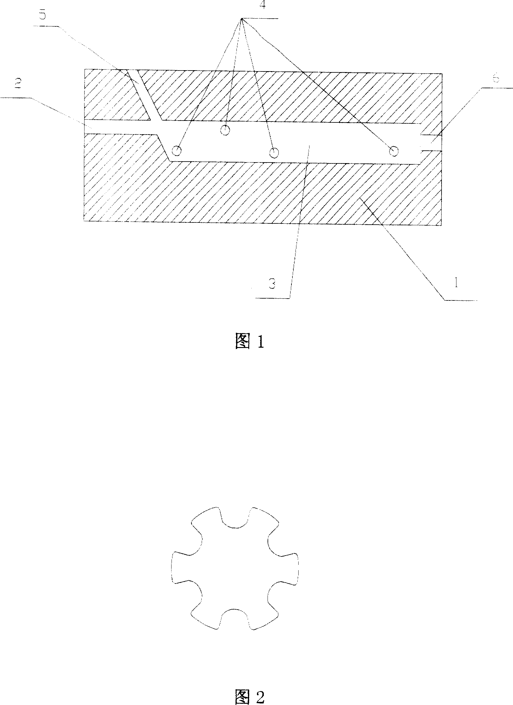
[0031] As shown in Fig. 1 and Fig. 2, a kind of impregnation equipment for preparing continuous long fiber reinforced thermoplastic resin comprises an impregnation equipment outer body (1); channel (2), the flow channel is placed horizontally, and the end is connected with the impregnation independent flow channel (3); a set of freely rotatable tension rollers is arranged in the impregnation independent flow channel (3), which consists of three tension rollers (4) , the end is also provided with a tension roller (4), and there are 6 arc-shaped grooves on the tension roller (4); the plane where the continuous long fiber inlet channel (5) is located has an angle with the horizontal plane; the impregnation outlet (6) is located at The end of the outer body (1) of the immersion equipment communicates with the independent flow channel (3) for immersion.

[0032] A bundle of continuous long fibers is introduced into the impregnated independent flow channel (3) through the continuous...


PUM

PropertyMeasurementUnit
widthaaaaaaaaaa
heightaaaaaaaaaa
diameteraaaaaaaaaa

Abstract

The present invention discloses a molding method and molding equipment for a continuous fiber reinforced thermoplastic resin. The molding equipment of the present invention comprises a melting soakage mould. The melting soakage mould comprises a soakage mould outer body and a thermoplasticity resin fused mass crack flow passage, a soakage independent flow passage, a continuous fiber inlet passage and a soakage outlet which are arranged in the soakage mould outer body. The thermoplasticity resin fused mass crack flow passage is arranged on upstream end and forms an angle with the continuous fiber inlet passage. The thermoplasticity resin fused mass crack flow passage and the continuous fiber inlet passage are both communicated with the soakage independent flow passage. The soakage outlet is arranged on downstream end and is communicated with the end of the soakage independent flow passage. The soakage independent flow passage is also provided with at least one tension roller group which is capable to rotate freely. Using the molding equipment of the present invention for manufacturing continuous fiber reinforced thermoplastic resin avoids the interference and impairment between fiber bundles, guarantees the stable and continuous production and improves the dipping effect, so fiber reinforced thermoplastic resin with excellent performance can be obtained.

Description

technical field [0001] The invention relates to continuous long fiber reinforced thermoplastic resin, in particular to a molding method and molding equipment for continuous long fiber reinforced thermoplastic resin. Background technique [0002] Continuous long fiber reinforced thermoplastic resin is a kind of reinforced thermoplastic resin whose reinforcing fibers are arranged in one direction and whose length is equal to the length of resin pellets. Compared with conventional short fiber reinforced thermoplastic resins, it has more excellent mechanical properties, dynamic fatigue resistance, warpage resistance, etc. Therefore, it is especially suitable to replace cast iron, aluminum and thermosetting plastics in some occasions. [0003] There have been some disclosed impregnation equipment and impregnation methods for preparing continuous long fiber reinforced thermoplastic resins. The common disadvantage of these forming methods is that the continuous fiber bundle canno...

Claims


Application Information

Patent Timeline
Patent Type & Authority Applications(China)
IPC IPC(8): B29C70/50B29C70/56B29C70/54B29B9/06
Inventor 黄险波姜苏俊曾祥斌陈大华刘志力万勇军
Owner KINGFA SCI & TECH CO LTD
Learn More