Circulating fluidized bed equipment and pine pollen production method thereof
A circulating fluidized bed and equipment technology, applied in chemical instruments and methods, lighting and heating equipment, applications, etc., can solve the problems of secondary pollution, high production costs, unreliable work, etc.
- Summary
- Abstract
- Description
- Claims
- Application Information
AI Technical Summary
Problems solved by technology
Method used
Image
Examples
no. 1 example
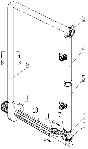
[0097] The first embodiment: a kind of circulating fluidized bed equipment designed according to the first technical scheme of the present invention.
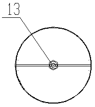
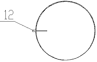
[0098] see Figure 1 to Figure 4 , the circulating fluidized bed equipment includes fan 1, positive pressure circulation pipe 2, dust collector branch, negative pressure circulation pipe 10; , there is a functional branch inlet interface between the head end and the tail end; the dust collector branch includes the dust collector 4, the dust collector 5, the discharge tee 6, the regulating valve 8 and the third discharge tee connected in sequence The discharge valve 7 installed on the mouth; the head end of the negative pressure circulation pipe 10 is the air inlet, and the tail end is the outlet, and a functional branch outlet interface is arranged between the head end and the tail end, and the negative pressure circulation pipe 10 is equipped with a feeding Valve 11; the above components are in accordance with the air outlet ...
no. 2 example
[0103] The second embodiment: a kind of circulating fluidized bed equipment designed according to the second technical scheme of the present invention.
[0104] see Figure 5 and Image 6 , the circulating fluidized bed equipment includes fan 21, positive pressure circulation pipe 22, sieve tube branch, negative pressure circulation pipe 28; , there is a functional branch inlet interface between the head end and the tail end; the sieve drum branch includes the screen drum 24, the screen drum 25, and the regulating valve 26 connected in sequence; the head end of the negative pressure circulation pipe 28 is the air inlet, and the tail The end is the outlet, and a functional branch outlet interface is provided between the head end and the tail end, and a feeding valve 27 is arranged on the negative pressure circulation pipe 28; The inlet interface of the functional branch of the circulation pipe 22, the branch of the dust collector, the outlet interface of the functional branch...
no. 3 example
[0106] The third embodiment: a kind of circulating fluidized bed equipment designed according to the third technical scheme of the present invention.
[0107] see Figure 7 to Figure 10 , the circulating fluidized bed equipment includes fan 31, positive pressure circulation pipe Ⅰ 32, cyclone dust collector 33, positive pressure circulation pipe Ⅱ 34, dust collector branch, negative pressure circulation pipe 312; The tail end of the pressure circulation pipe II 34 is a cleaning port, and a valve 35 is installed at the cleaning port, and a functional branch inlet interface is provided between the head end and the tail end of the positive pressure circulation pipe II 34; the dust collector branch includes dust collectors 36, Dust collector 37, discharge tee 38, regulating valve 310 and discharge valve 39 installed on the third port of discharge tee 38; the head end of negative pressure circulation pipe 312 is the air inlet, the tail end is the outlet, There is a functional bran...
PUM
 Abstract
Description
Claims
Application Information
 - Generate Ideas
- Intellectual Property
- Life Sciences
- Materials
- Tech Scout
- Unparalleled Data Quality
- Higher Quality Content
- 60% Fewer Hallucinations
Browse by: Latest US Patents, China's latest patents, Technical Efficacy Thesaurus, Application Domain, Technology Topic, Popular Technical Reports.
© 2025 PatSnap. All rights reserved.Legal|Privacy policy|Modern Slavery Act Transparency Statement|Sitemap|About US| Contact US: help@patsnap.com


