
Method for forming peelable elastomer mask plate on surface of polymer base materials

A technology of substrate surface and elastic body, which is applied in the field of masks, can solve problems such as difficult fixing, inability to restore graphics well, large hole spacing of mask templates, etc., and achieve the effect of avoiding difficulties

Inactive Publication Date: 2014-02-12
西安宙斯光电科技有限公司
View PDF3 Cites 13 Cited by
  • Summary
  • Abstract
  • Description
  • Claims
  • Application Information

AI Technical Summary

Problems solved by technology

[0004] However, the current technology is still far from practical application.
Because the polydimethylsiloxane elastomer is too soft and easily deformed under external force, it is actually difficult to spread the prefabricated polydimethylsiloxane elastic mask well on the processing surface
At the same time, in the process of peeling and spreading, the fine pattern openings formed on the polydimethylsiloxane mask will be deformed by external force, which cannot well restore the formation of polydimethylsiloxane mask. time graphics
In the existing reports, in order to ensure sufficient mechanical strength and avoid deformation of the openings on the polydimethylsiloxane mask, the actually manufactured mask has a very large hole spacing.
As a result, although very small openings can be formed on the polydimethylsiloxane mask, such as circular holes with a diameter of 5 μm, the density of the openings is very small and cannot provide sufficient component density.
The polydimethylsiloxane mask is flexible, but there are few reports on its application on soft and easily deformable substrates such as plastics, which is caused by the easy deformation of the polydimethylsiloxane mask. difficult to process
Another reason for the aforementioned problems is that the polydimethylsiloxane mask does not adhere well enough to the applied substrate and is difficult to fix
Therefore, there is no suitable mask technology suitable for flexible substrates that are easily bent and deformed.

Method used


Image

  • Method for forming peelable elastomer mask plate on surface of polymer base materials
  • Method for forming peelable elastomer mask plate on surface of polymer base materials

Examples


Embodiment 1

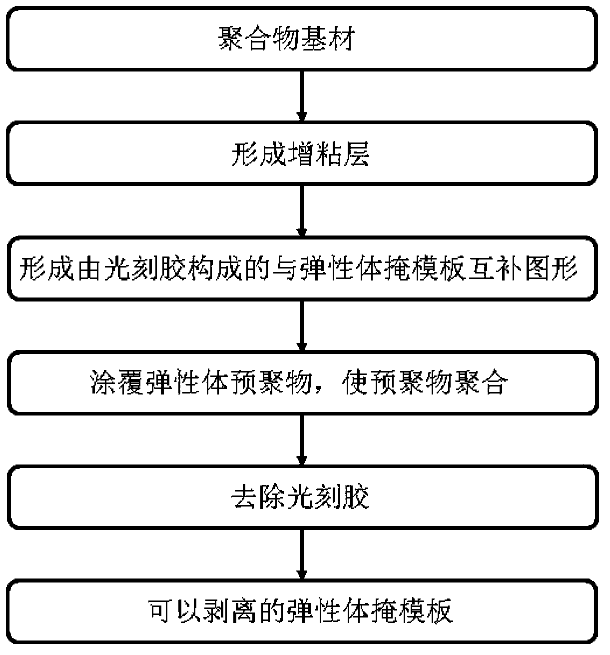
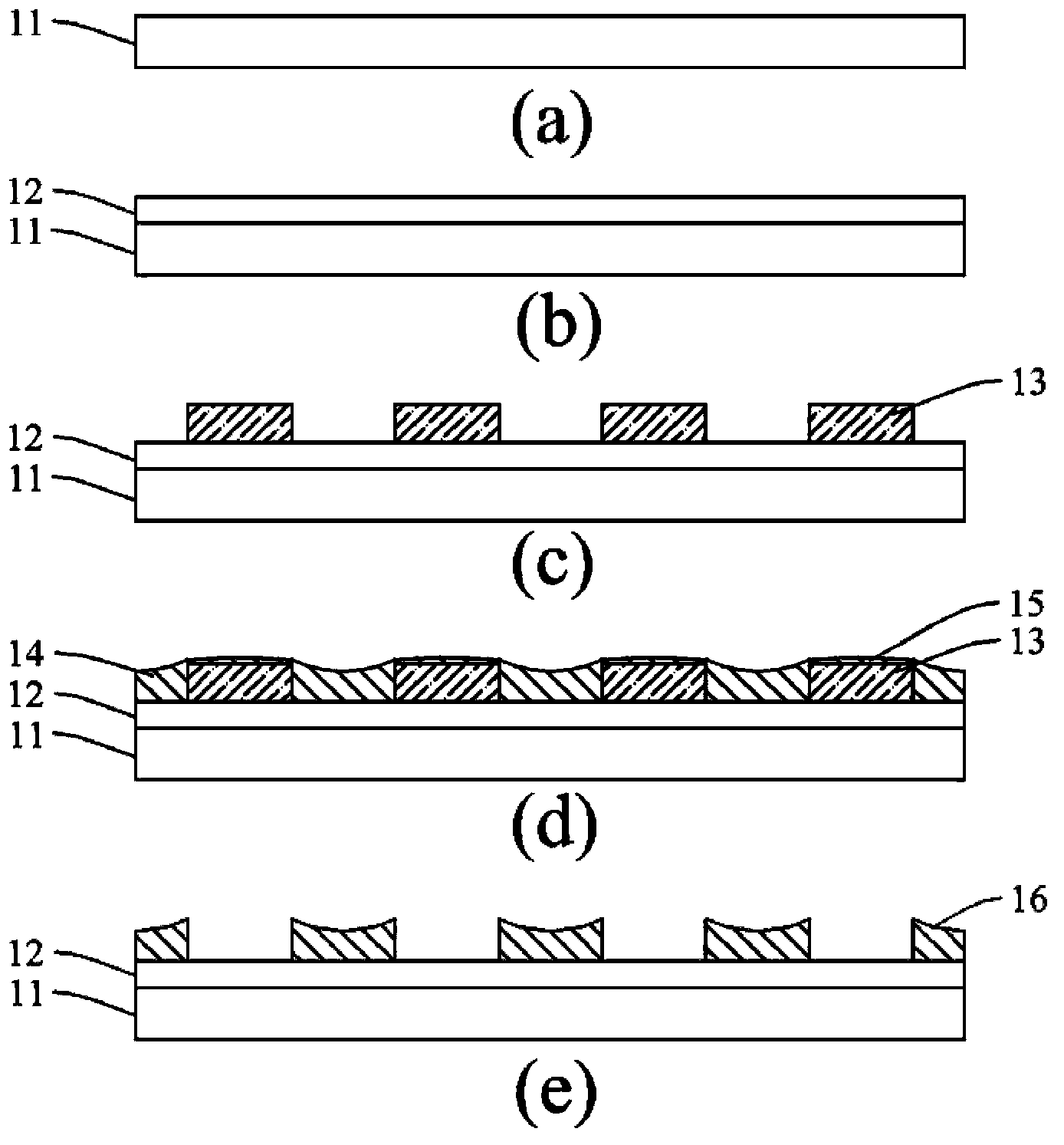
[0028] A 188-micron thick PET (polyethylene terephthalate) film is used as the substrate 11 (polymer substrate), and a layer of 50 micron ZrO is deposited on the surface of the substrate 11 by magnetron sputtering. 2 The film serves as the adhesion promoting layer 12 . deposited ZrO 2 The power used for the film is 100 watts, the background gas is Ar gas, and the pressure is 7.2×10 -1 Pa, the deposition time is 10 minutes. After that, the deposited ZrO 2 A negative photoresist is coated on the film with a coater. The coated photoresist was baked on a hot plate at 70 degrees for 2 hours, and the thickness of the photoresist was 90 microns. During exposure, the aperture width of the chrome mask used is 100 microns, and the aperture pitch is 100 microns. The light intensity of the exposure was 25 mW / cm2, and the exposure time was 120 seconds. Place the exposed plastic substrate in tetramethylammonium hydroxide for development to form the required photoresist pattern 13 . T...


PUM

PropertyMeasurementUnit
Thicknessaaaaaaaaaa
Thicknessaaaaaaaaaa

Abstract

The invention discloses a method for forming a peelable elastomer mask plate on the surface of polymer base materials. The method comprises the steps that firstly, a coating layer for improving caking property is preformed on the surface of the polymer base materials; secondly, patterns, complementary with the mask plate, formed by photoresist are formed on the surface of the polymer base materials through the photolithography technique; thirdly, an elastomer coating layer with a certain thickness is formed again; fourthly, the photoresist is removed, and the peelable elastomer mask plate is obtained. The elastomer mask plate is used for forming patterned photoelectric functional devices on the polymer base materials.

Description

【Technical field】 [0001] The invention relates to a mask board which can be applied to the manufacture of organic thin-film optical and electrical devices, such as organic electroluminescent diodes and organic thin-film transistors. 【Background technique】 [0002] In recent years, reports on the use of organic elastomers to form fine masks to manufacture organic thin-film optical and electrical devices have gradually increased. For example, George M.Whitesides et al. reported in Advanced Materials (1996, No.11, 546-552) that a strippable polydimethylsiloxane (PDMS) elastomer formed on a silicon wafer through a photoresist Mask method. By peeling off the mask from the silicon wafer and applying it on the ITO glass, it can be used as a mask to manufacture organic electroluminescent diode devices with specific patterns. In the report of Richard B. Kaner et al. in Advanced Materials (2010, No.22, 897–901), they further used the PDMS elastomer mask as a screen printing mask to ...

Claims


Application Information

Patent Timeline
IPC IPC(8): H01L51/56G03F7/00G03F7/42
CPCG03F7/00G03F7/42H10K71/233
Inventor 闵军辉张莹苏璇
Owner 西安宙斯光电科技有限公司
Learn More