
Nuclear fuel rod with ceramic cladding and metallic pellet

A technology of nuclear fuel rods and metal fuels, which is applied in the fields of reactor fuel material, nuclear power generation, surveying and navigation, etc., can solve the problem that the cladding and fuel neutronics, mechanical properties have not been improved, and the thermal conductivity cannot be fundamentally improved. Thermal conductivity, poor mechanical properties and other problems, to achieve the effect of improving mechanical properties, high temperature resistance, and increasing working temperature

Active Publication Date: 2013-09-11
SHANGHAI NUCLEAR ENG RES & DESIGN INST CO LTD +1
View PDF8 Cites 16 Cited by
  • Summary
  • Abstract
  • Description
  • Claims
  • Application Information

AI Technical Summary

Problems solved by technology

Although the above design increases the heat transfer capacity of the fuel rod by changing the structure of the fuel rod, increasing the heat transfer area, etc., it fails to fundamentally improve its heat conduction capacity, and the neutronics and mechanical properties of the cladding and fuel have not been improved. improve
In general, the thermal conductivity and mechanical properties of existing fuel rods are poor, and the cladding is prone to damage under high temperature and irradiation conditions

Method used


Image

  • Nuclear fuel rod with ceramic cladding and metallic pellet
  • Nuclear fuel rod with ceramic cladding and metallic pellet
  • Nuclear fuel rod with ceramic cladding and metallic pellet

Examples


Embodiment Construction

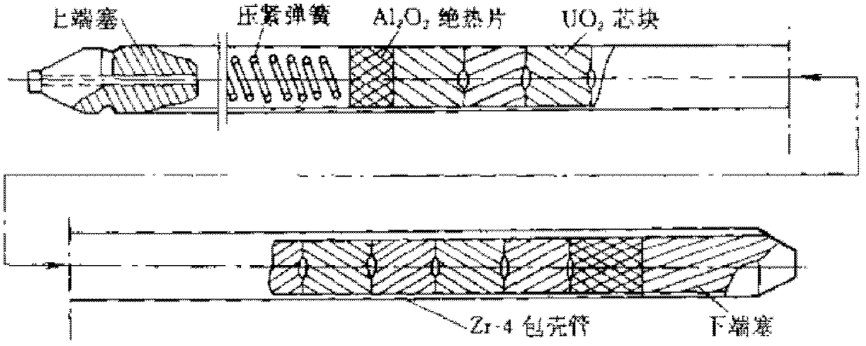
[0031] Such as image 3 As shown, the nuclear fuel rod of the present invention is provided with the lower end plug 5, the shielding area 4 adjacent to the lower end plug 5, the active fuel area 3 adjacent to the shielding area 4, and the extension above the active fuel area 3 in the axial direction. The air cavity 2 and the upper end plug 1 adjacent to the upper end of the elongated air cavity 2 . The length of the extended air chamber 2 is much longer than that of the existing PWR fuel rod air chamber, and is also longer than that of the existing fast reactor fuel rod air chamber, and its length is about 1 to 1.5 times the length of the fuel rod active area 3 .

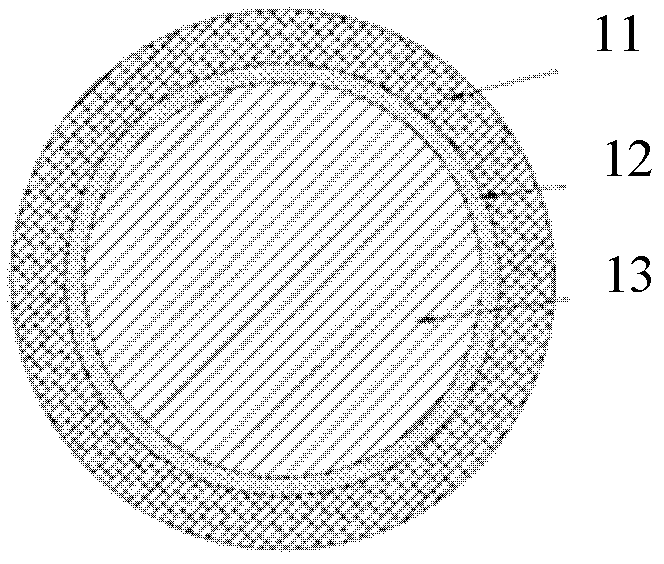
[0032] figure 2 is a cross-sectional view of the active fuel zone 3 . Such as figure 2 and image 3 In the shown embodiment, the elongated gas cavity 2 is elongated relative to the gas cavity of the existing fuel rod, so as to provide sufficient containment capacity of fission gas.

[0033] Such as image 3 ...


PUM


Abstract

The invention aims at providing a nuclear fuel rod with ceramic cladding and metallic pellet. The nuclear fuel rod with ceramic cladding and metallic pellet has the advantages that the heat-conducting property of the nuclear fuel rod can be improved, the central temperature of the fuel pellet is lowered or the fuel power density is effectively improved, the fuel rod cladding mechanical property, corrosion resistance and radiation resistance are greatly improved, the breakage rate of the fuel rod is lowered, the discharge burnup of the fuel rod is remarkably increased and the fuel utilization rate is greatly improved; meanwhile, the fuel rod has good neutronics performance, and can be widely used in a fast reactor or a thermal reactor. The cladding of the nuclear fuel rod provided by the invention is a SiCf / SiC composite ceramic material cladding, the metallic fuel pellet adopts a U-Zr or U-Pu-Zr alloy fuel pellet; a gap between the cladding and the fuel pellet is filled with low-melting-point metal; and a lengthened air cavity is designed at the upper part of the fuel rod.

Description

technical field [0001] The invention relates to a fuel rod in the field of nuclear reactor engineering, which can be used as a core fuel rod of a fast neutron reactor or a thermal neutron reactor. Background technique [0002] Nuclear fuel rods are the basic unit for releasing energy in a nuclear reactor. A certain number of fuel rods are assembled through structural parts such as bases and grids to form fuel assemblies, and the nuclear reactor core is composed of these fuel assemblies. Nuclear fuel rods are generally composed of fuel pellets and cladding, and there is generally a certain gap between the pellets and the cladding. At the same time, there is still a cavity on the upper part of the fuel rod, which is used to accommodate the fission gas produced by the fuel rod during the long-term nuclear reaction. [0003] Fuel pellets are the actual exothermic nuclear fuel elements. The most common fuel pellets are UO formed by powder metallurgy and high temperature sinteri...

Claims


Application Information

Patent Timeline
IPC IPC(8): G21C3/07G21C3/60
CPCY02E30/30
Inventor 司胜义陈其昌赵金坤卑华
Owner SHANGHAI NUCLEAR ENG RES & DESIGN INST CO LTD
Learn More