
Method and device for continuously preparing high-silicon steel ribbon under magnetic field

A high-silicon steel and thin strip technology, applied in coatings, electrolytic coatings, etc., can solve the problems of inability to carry out large-scale production, poor silicon uniformity, poor process continuity, and poor density, and achieve stable and controllable production processes. Reduce production costs and have little impact on the original structure

Active Publication Date: 2013-02-13
SHANGHAI UNIV
View PDF6 Cites 33 Cited by
  • Summary
  • Abstract
  • Description
  • Claims
  • Application Information

AI Technical Summary

Problems solved by technology

The powder metallurgy method requires steps such as powder mixing, compression molding, sintering, multi-pass rolling, coating of MgO powder insulation layer, and secondary sintering. The process is complicated, and the uniformity of silicon and the continuity of the process are poor. High energy consumption, and still limited by the brittleness of silicon steel
The thin-strip silicon steel produced by the CVD method developed by Japan's NKK company has good magnetic properties and has been industrialized on a small scale, but there are high deposition temperatures, high energy consumption, poor surface quality of silicon steel, need for warm rolling and smoothing, and iron loss. serious disadvantages such as while SiCl 4 It is highly corrosive, and it will produce hydrochloric acid mist when it encounters water vapor, and the reaction product FeCl 2 Exhaust gas pollutes the environment and cannot be mass-produced
In addition, there are PCVD method, molten salt electrodeposition method, laser cladding spraying method and electron beam physical vapor deposition method, etc., but the above methods still need to be further improved in terms of production process controllability, cost and environmental protection.

Method used


Image

  • Method and device for continuously preparing high-silicon steel ribbon under magnetic field

Examples


Embodiment 1

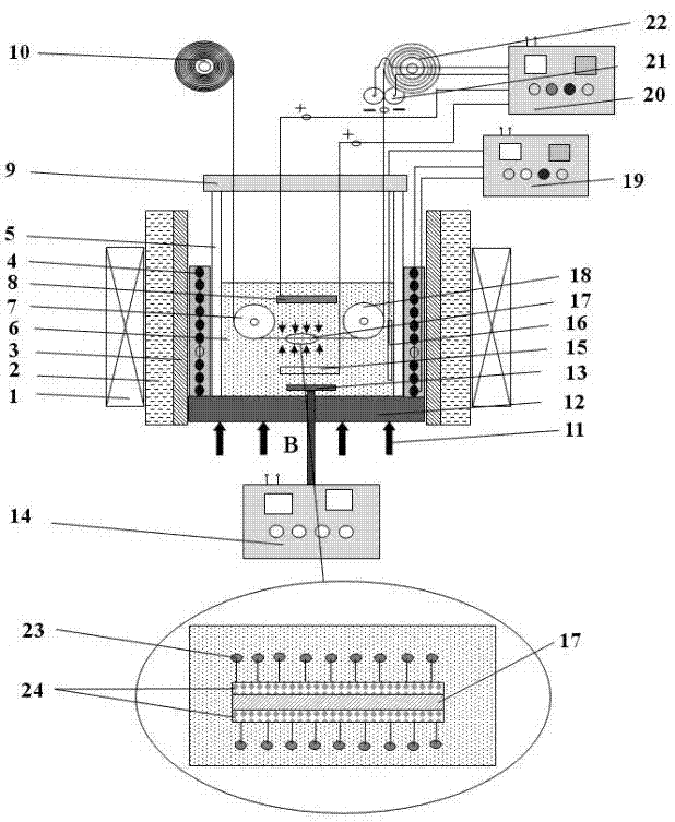
[0027] 1. A method for continuously preparing high-silicon steel thin strips under a magnetic field, which is characterized in that ferrosilicon alloy powder with a particle size of 0.1-3 μm and a relatively high silicon concentration-silicon content of 7.0-99wt% Si(23), is added with a special dispersant In the composite iron plating electrolyte, the low-silicon steel strip (17) with a silicon content of 0.1-4% Si is used as the cathode, and the pure iron sheet or low-silicon steel strip is used as the anode (8,15). When the low-silicon steel strip is continuously When passing through the middle of the double anode, the electroplating power supply (20) is turned on, and at the same time, the magnetization of the low-silicon steel thin strip cathode by an external magnetic field is used to form a strong magnetic field gradient and magnetic field force on the surface of the low-silicon steel thin strip cathode, and the composite iron plating electrolyte The fine ferrosilicon all...

Embodiment 2

[0034] This embodiment is basically the same as Embodiment 1, and the features are as follows:

[0035] 1. The magnetic field generation method of the constant magnetic field generator (1) is a permanent magnet, or an electromagnet, or a Bitter magnet, or a superconducting magnet, or a mixed magnet, and the magnetic induction is 0.001-20 Tesla (T) ;

[0036] 2. The low-silicon steel strip cathode (17) has a thickness of 0.05-0.5mm and a width of 10-2000mm.

[0037] 3. The stirring method of the electroplating solution (6) is mechanical stirring, or ultrasonic stirring, or stirring by acid pump circulation, so that the composition, temperature and composition of the electroplating solution (6) are homogenized.

[0038] 4. The composite plating process is carried out continuously, and the speed of the low-silicon steel strip cathode (17) is controlled at 0.01-10m / s; the distance between the cathode and the anode is kept at 0.5-10cm.

[0039] 5. The thickness of the composite i...

Embodiment 3

[0044] see figure 1 , a device for continuously preparing high-silicon steel thin strips under this magnetic field, applied to the above method, including

[0045] Constant magnetic field generator (1), water cooling device (2), heat insulating material (3), heating device (4), temperature-resistant electroplating tank (5), electroplating solution (6), front guide fixed pulley (7), pure iron On-chip anode (8), electroplating tank cover (9), high-silicon coated silicon steel strip winding mechanism (10), polytetrafluoroethylene bottom (12), mechanical stirring paddle (13), mechanical stirring control device (14), Pure iron lower anode (15), thermocouple (16), low-silicon steel strip cathode (17), rear guide fixed pulley (18), temperature controller (19), DC power supply (20), cathode electric nip roller (21 ), low-silicon steel delivery mechanism (22). The temperature-resistant electroplating tank (5) is placed on the polytetrafluoroethylene bottom plate (12), and the periph...


PUM

PropertyMeasurementUnit
Thicknessaaaaaaaaaa
Magnetic inductionaaaaaaaaaa
Thicknessaaaaaaaaaa

Abstract

The invention provides a method and a device for continuously preparing a high-silicon steel ribbon under a magnetic field. The method adopts a composite plating method and comprises the following steps of adding 0.1-3mum of ferrosilicon powder in an iron plating solution, using a low-silicon steel strip as an electrolytic cathode, plating 7.0-99 wt % of thick composite plating layer of Si in the composite electrolytic solution, obtaining uniform 6.5 wt% of high-silicon steel ribbon of the Si after thermal treatment, and carrying out continuous preparation. According to the device provided by the invention, on the basis of the traditional composite plating device, a constant magnetic field of which the magnetic field strength is 0.01-20 T is applied, the low-silicon steel ribbon which is used as a cathode is magnetized through the magnetic field, a stronger gradient field is formed on the surface, ferrosilicon particles in a plating solution are adsorbed to the surface of the cathode of the low-silicon steel strip by utilizing a magnetic field force, thus a high-silicon plating layer can be obtained through a composite iron plating process, and then, the high-performance high-silicon steel ribbon of which the silicon content is up to 6.5 wt% can be prepared through follow-up climate protection thermal treatment. The method and the device, disclosed by the invention, have the advantages that the operation is simple, the low-temperature silicon increasing operation is carried out, the cost is low, and the high-silicon steel ribbons can be continuously prepared.

Description

technical field [0001] The invention relates to a method and device for continuously preparing high-silicon steel strips under a magnetic field. The invention belongs to the technical field of magnetic material preparation and composite electroplating. Background technique [0002] Silicon steel is the soft magnetic material with the largest output and consumption in the fields of electricity and magnetism. It is widely used in the field of energy conversion in electric power, electronics and military industries. Therefore, it is also an important metal functional material with great potential for energy saving. It has been known in theory for a long time that if the silicon content in silicon steel is increased to 6.5%, the magnetostriction can approach zero and the magnetic properties will be the best. However, when the silicon content exceeds 4wt%, as the silicon content increases, the material becomes brittle, making it difficult to perform rolling and stamping. [00...

Claims


Application Information

Patent Timeline
IPC IPC(8): C25D5/00C25D15/00
Inventor 钟云波龙琼周鹏伟孙宗乾郑天翔
Owner SHANGHAI UNIV
Learn More