
Solid oxide fuel cell composite cathode and preparation method thereof

A technology of solid oxide and composite cathode, which is applied in the direction of battery electrodes, circuits, electrical components, etc., can solve the problems of severe sintering, decrease in electrode porosity, performance attenuation, etc., and achieve high porosity, good thermal stability, and high electrical The effect of chemical properties

Inactive Publication Date: 2012-09-19
NANJING UNIV OF TECH
View PDF4 Cites 24 Cited by
  • Summary
  • Abstract
  • Description
  • Claims
  • Application Information

AI Technical Summary

Problems solved by technology

However, one disadvantage of the impregnation method is that it may lead to a serious decrease in the porosity of the electrode, which in turn has a serious impact on the mass transfer of the electrode.
In addition, nanoelectrodes have a big disadvantage of low thermal stability
Nanoparticles are unstable substances with high surface energy. At the operating temperature of SOFCs, coupled with the action of polarization current, the sintering between nanoparticles becomes very serious, resulting in significant performance degradation.
Therefore, the application of cathodes prepared by the traditional impregnation method in SOFCs is greatly limited.

Method used


Image

  • Solid oxide fuel cell composite cathode and preparation method thereof
  • Solid oxide fuel cell composite cathode and preparation method thereof
  • Solid oxide fuel cell composite cathode and preparation method thereof

Examples


Embodiment 1

[0024] Example 1: Preparation of electrolyte material Sm 0.2 Ce 0.8 o 1.9 For the porous framework, SrCoO 3 The powder suspension is the composite cathode of the impregnating liquid.

[0025] Proceed as follows:

[0026] (1) Preparation of three-dimensional porous electrolyte framework: the electrolyte material Sm 0.2 Ce 0.8 o 1.9 To make a porous skeleton, see the published literature for detailed manufacturing steps of the skeleton: F.Zhao, R.R.Peng, C.R.Xia, Fuel Cells Bull.2(2008) 12-16. The firing temperature of the skeleton in this example is 1250°C / 5h , to obtain a three-dimensional porous electrolyte framework with a thickness of 20 μm and a porosity of 50%.

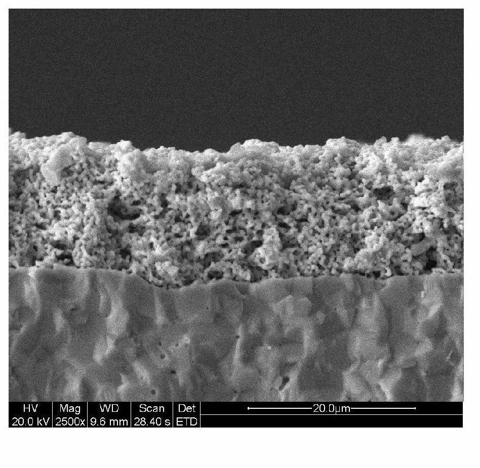
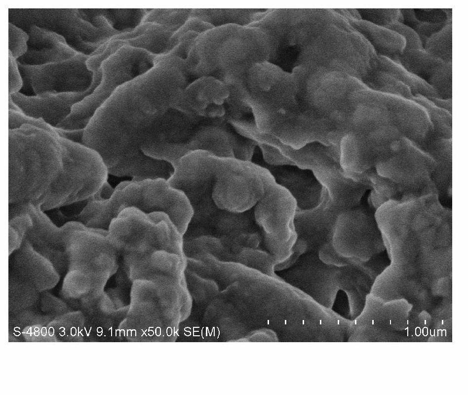
[0027] figure 1 Sm shown 0.2 Ce 0.8 o 1.9 The electrolyte material is a microscopic morphology diagram of a porous skeleton; it can be seen from the figure that the skeleton prepared by this method has an ideal effect, the pore size distribution in the skeleton is relatively uniform, and the pore size ...

Embodiment 2

[0032] Example 2: Preparation of Sm 0.2 Ce 0.8 o 1.9 The electrolyte material is a porous framework, Co(NO 3 ) 3 and Sr(NO 3 ) 3 The solution is the compound cathode of the immersion liquid.

[0033] Proceed as follows:

[0034] (1) Preparation of three-dimensional porous electrolyte framework: the electrolyte material Sm 0.2 Ce 0.8 o 1.9 To make a porous skeleton, the manufacturing steps of the skeleton are the same as in Example 1, except that the firing temperature of the skeleton in this example is 1300°C / 5h, and a three-dimensional porous electrolyte skeleton with a thickness of 15 μm and a porosity of 45% is obtained.

[0035] (2) Prepare a nitrate solution for impregnating the cathode material: Sr(NO 3 ) 3 and Co(NO 3 ) 2 ·6H 2 O is mixed into deionized water according to the molar ratio of metal ions Sr and Co as 1:1, then glycine is added according to the molar ratio of total metal ions to glycine as 1:2, and finally the concentration of the solution is ...

Embodiment 3

[0039] Embodiment 3: prepare with BaZr 0.1 Ce 0.7 Y 0.2 o 3-δ The electrolyte material is a porous framework, Co(NO 3 ) 3 The solution is the compound cathode of the immersion liquid.

[0040] Proceed as follows:

[0041] (1) Preparation of three-dimensional porous electrolyte framework: the electrolyte material BaZr 0.1 Ce 0.7 Y 0.2 o 3-δ Do porous skeleton, the manufacture step of skeleton in the present embodiment and the Sm in embodiment 1 0.2 Ce 0.8 o 1.9 The steps for making a skeleton are the same. In this example, the firing temperature of the skeleton was 1400°C / 4h, and a three-dimensional porous electrolyte skeleton with a thickness of 30 μm and a porosity of 40% was obtained.

[0042] (2) Prepare a nitrate solution for impregnating the cathode material: Co(NO 3 ) 2 ·6H 2 O was added to deionized water, and then a certain amount of glycine was added to make the molar ratio of Co metal ions to glycine 1:2, and the concentration of the solution was adju...


PUM

PropertyMeasurementUnit
Thicknessaaaaaaaaaa
Polarization resistanceaaaaaaaaaa
Porosityaaaaaaaaaa

Abstract

The invention belongs to the field of solid oxide fuel cells and particularly relates to a solid oxide fuel cell composite cathode and a preparation method thereof, wherein the solid oxide fuel cell composite cathode has a high electrochemistry performance and is stable in long-time operation. The preparation method includes the following steps of step one, preparing a three-dimensional porous skeleton made of electrolytic materials at a high temperature; step two, preparing a powder suspension or a nitrate solution of a cathode material; step three, impregnating the powder suspension or the nitrate solution into the porous skeleton and then calcinating the porous skeleton; step four, repeating the operation of the step 3 for a plurality of times until the impregnating quantity reaches the requirement; step five, performing high temperature sintering under an air atmosphere to obtain the three-dimensional composite cathode with a core-shell structure. According to the solid oxide fuel cell composite cathode and the preparation method thereof, the process is simple, expensive experiment apparatuses are not required, the obtained composite cathode is of the core-shell structure, a core is the electrolytic skeleton, a shell is a phase reaction layer with a stable nano thin film structure, and the problem that the performance is attenuated due to the fact that nano particles of the solid oxide fuel cell composite cathode prepared by an impregnating method are low in stability and easy to sinter is solved.

Description

technical field [0001] The invention belongs to the field of solid oxide fuel cells, in particular to a solid oxide fuel cell composite cathode with high electrochemical performance and stable long-term operation and a preparation method thereof. Background technique [0002] The classic solid oxide fuel cell cathode material is the oxide La with a perovskite crystal phase structure 0.8 Sr 0.2 MnO 3 (LSM), which has good electronic conductivity, a thermal expansion coefficient that matches traditional electrolytes, and high thermochemical stability, etc., is still widely used in high-temperature SOFCs. However, due to the pure electronic conductivity of LSM, the electrode reaction is confined to the LSM-electrolyte-air three-phase interface. At high temperature, the electrode reaction can maintain a fast rate, so the polarization resistance of the LSM electrode can be controlled within a reasonable range. However, as the temperature decreases, the activity of the electro...

Claims


Application Information

Patent Timeline
IPC IPC(8): H01M4/86H01M4/88
CPCY02E60/50
Inventor 邵宗平王富存陈登洁
Owner NANJING UNIV OF TECH
Learn More