
Laser-propelling-based method and laser-propelling-based device for producing sheet shock forming limit diagram

A technology of impact forming and laser impact, which is applied in laser welding equipment, manufacturing tools, welding equipment, etc., can solve the problems of poor directionality of laser beam impacting sheet metal, high cost of mold making, long replacement time, etc., and achieves easy measurement Ultimate strain point, avoid excessive impact phenomenon, simple test process

Inactive Publication Date: 2012-06-27
JIANGSU UNIV
View PDF3 Cites 9 Cited by
  • Summary
  • Abstract
  • Description
  • Claims
  • Application Information

AI Technical Summary

Problems solved by technology

[0003] When laser shocking sheet metal is formed, often because of the excessive pressure of the shock wave during the impact forming process, it is easy to cause the sheet metal to be broken or deformed such as necking, so it is necessary to explore the forming performance of the sheet metal under laser shock Criterion - laser shock forming limit diagram; the forming limit diagram of laser shock metal sheet cannot be replaced by the forming limit diagram of stamping metal sheet by traditional pressure processing technology, because laser shock sheet forming has ultra-high pressure, fast and high strain The traditional pressure processing technology does not have these characteristics; the laser beam is directly impacted on the metal sheet, the sheet is severely cracked, and there are explosive cracks around it, and the ultimate strain value at the rupture cannot be accurately measured, and laser beam impact The directionality of the sheet metal is not good, it is easy to punch in the wrong direction, and the experimental sheet is wasted, so the forming limit diagram (FLD) obtained is not very accurate, and it cannot accurately predict and control the high strain rate formability of the laser shock sheet.
Domestic Jiangsu University Jiang Yinfang and others applied for the invention patent "Laser Shock Sheet Forming Limit Diagram Production Method and Data Acquisition Device", patent authorization number: 200910264808.X, this patent needs to manufacture elliptical dies with different ellipticities, which is not easy To produce a suitable ellipse, the mold making cost is high, the replacement time is long, and because the laser shock metal sheet forming has a high strain rate, the strain difference in each direction is small, and the difference in the direction of the long and short axes of the ellipse is also small

Method used


Image

  • Laser-propelling-based method and laser-propelling-based device for producing sheet shock forming limit diagram
  • Laser-propelling-based method and laser-propelling-based device for producing sheet shock forming limit diagram
  • Laser-propelling-based method and laser-propelling-based device for producing sheet shock forming limit diagram

Examples


Embodiment 1

[0035] Such as Figure 7 , 8 shown.

[0036] A method based on laser propulsion to make a limit diagram of sheet metal impact forming, including data collection and drawing of the limit diagram of sheet metal impact forming, which is characterized in that the shock wave generated by the repetition frequency pulse laser is used to propel the bullet, and the momentum generated by the bullet acts on different widths On the sheet, the bullet guide structure ensures the point and direction of the impact force, so that the deformation of the sheet is uniform and the data can be measured. The specific steps are as follows:

[0037] (1) Print a fine circular grid on the sheet;

[0038] (2) Cut the printed grid sheet into different widths;

[0039] (3) Put the above sheets on the die, the side without mesh is opposite to the bullet, and press it to death with a blank holder with calendering ribs;

[0040] (4) Fabricate propelling bullets, coat them with absorbing layers, and mount ...

Embodiment 2

[0048] Such as Figure 1~8 shown.

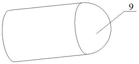
[0049] A device based on laser propulsion to produce sheet metal impact forming limit diagrams, which includes a central control processor 1, a laser controller 2, a repetition rate pulse laser 3, a spot adjustment device 4, glass 5, black paint coating 6, a bracket 7, 8. Bullet 9, blank holder 10, sheet material 11, die 12, multi-axis coordinate table 13, ultrasonic thermal imaging detector 14, coordinate axis rotation controller 15. It is characterized in that the central control processor 1 is electrically connected with the laser controller 2, the ultrasonic thermal imaging detector 14 and the coordinate axis rotation controller 15, the output of the laser controller 2 is connected with the input of the repetition frequency pulse laser 3, and the glass 5 is fixed on the On the brackets 7 and 8, bullets 9 covered with black paint coating 6 are put into the brackets 7 and 8 on the side facing the laser beam and close to the glass 5 to for...


PUM


Abstract

The invention relates to a method and a device of forming a limit diagram in the technical field of laser shock sheet forming, in particular to a laser-propelling-based method and a laser-propelling-based device for producing a sheet shock forming limit diagram, which are mainly used for judging failure and deformation of sheets such as necking or cracking and for evaluating forming performance of the sheets. The method is characterized in that: a laser controller (2) controls a repeatable frequency pulse laser device (3) to transmit laser beam of a certain laser pulse width, a facular adjusting device adjusts the diameter of a facular, the laser beam acts on a bullet, the bullet produces momentum under the laser effect to act on different sheets with different widths, a bullet guide structure is changed along with different width of the sheets, the bullet guide structure guarantees an acting force and an acting direction of a shock force, so the sheets are uniform to deform; and by changing the length-to-width ratio of the sheets (11), different limit stress points under different stress ratios can be obtained so as to obtain the forming limit diagram of the sheets.

Description

technical field [0001] The invention relates to a method and a device for making a sheet metal forming limit diagram, in particular to a method and a device for making a sheet metal impact forming limit diagram based on laser propulsion. Background technique [0002] Laser shock sheet forming is a composite forming technology that integrates material modification, strengthening and forming. It has the characteristics of ultra-high pressure, fast speed and high strain rate. It has a wide range of potential applications in many fields such as automobiles, aviation and defense industries. prospect. However, the research on laser shock forming has just started, and many problems such as forming fracture have been encountered, and the development of technology has encountered a bottleneck. The forming limit diagram is an important criterion for evaluating the formability of materials, so it is necessary to study and ensure the good formability of sheet metal in high strain rate ...

Claims


Application Information

Patent Timeline
Patent Type & Authority Applications(China)
IPC IPC(8): B23K26/00B23K26/42B21D26/00
Inventor 姜银方周群立汪建敏张青来张梦蕾姜文帆崔会杰程科升万里赵龑
Owner JIANGSU UNIV
Learn More