
Glass cloth for printed wiring board

A glass fiber cloth and glass technology, applied in the directions of printed circuits, printed circuits, printed circuit components, etc., can solve the anisotropy of dimensional change, the gap of reinforcement effect becomes larger, and the anisotropy improvement of dimensional change rate cannot be fully improved. effect, etc., to achieve the effect of less anisotropy and no warping/distortion

Active Publication Date: 2012-05-30
ASAHI KASEI KK
View PDF24 Cites 24 Cited by
  • Summary
  • Abstract
  • Description
  • Claims
  • Application Information

AI Technical Summary

Problems solved by technology

[0009] However, in general, glass fiber cloth is produced as a long-warp product with tension applied in the warp direction, so even if the warp and weft are woven with the same type of yarn and the same weaving density, there is a tendency to , that is, the untensioned weft yarns have larger undulations (Japanese: うねり) than the tensioned warp yarns
As a result, resulting in an anisotropic dimensional change
In addition, when making prepregs, the resin is impregnated and dried under tension applied in the warp direction. Therefore, depending on the magnitude of the tension, since the fluctuations in the warp direction are eliminated, it is different from the fluctuations in the weft direction. The difference in state becomes larger, and there is a tendency for the gap in reinforcement effect to become larger
In addition, in a thin glass fiber cloth with a thickness of 40 μm or less, the glass yarns constituting it are thin and have weak rigidity. Therefore, there is a problem that the tension applied in the warp direction during weaving or prepreg production has a negative effect on the fabric. The influence of anisotropy increases with thinning, and the problem of anisotropy in dimensional changes becomes more prominent
[0026] However, since the mechanical strength and elongation characteristics in the warp and weft directions are also affected by the rigidity and undulations of the yarn, in the case of reducing the distance between the yarns only by fiber opening treatment, the dimensional change rate in each direction The opposite sex improvement can not get sufficient effect
[0027] As mentioned above, the current situation is that there has been no glass fiber cloth of 40 μm or less that can accurately manufacture printed circuit boards with less anisotropy in dimensional changes and no warping / twisting. The glass fiber cloth is expected

Method used


Image

  • Glass cloth for printed wiring board
  • Glass cloth for printed wiring board
  • Glass cloth for printed wiring board

Examples


Embodiment 1

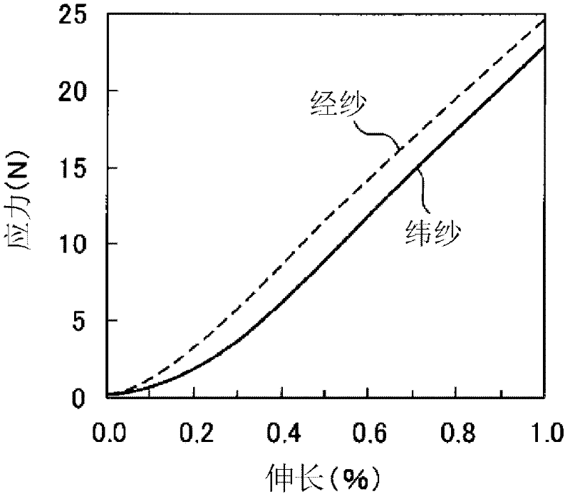
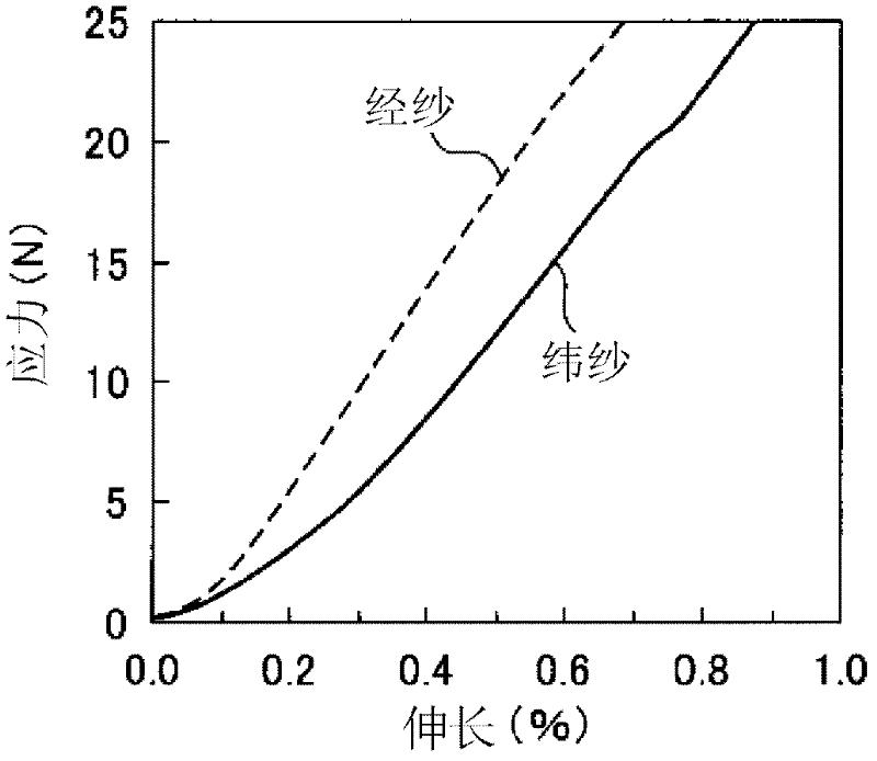
[0102] The warp uses an average single fiber diameter of 4.0 μm, the number of single fibers is 100, the number of twists is 1.0Z, and the weight per unit length is 3.4×10 -6 kg / m glass yarn, the weft yarn uses an average single fiber diameter of 4.5μm, the number of single fibers is 100, the number of twists is 1.0Z, and the weight per unit length is 4.2×10 -6 kg / m glass yarn was woven into a glass fiber cloth using an air jet loom at a weaving density of 75 warp yarns / 25mm and weft yarn 40 yarns / 25mm. The gray cloth obtained was heat-treated at 400° C. for 24 hours to desizing. Next, the glass fiber cloth was dipped in a treatment liquid using SZ6032 (manufactured by Toray Dou Corning Co., Ltd.) as a silane coupling agent, and after pressing (Japanese: relatively liquid), it was dried at 120° C. for 1 minute, and Fiber opening processing is carried out by using columnar flow to obtain a weight per unit area of ​​15g / m 2 1. Glass fiber cloth A with a thickness of 17 μm. Th...

Embodiment 2

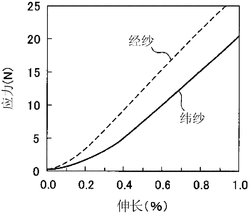
[0107] Except that the weaving density of the weft yarn is 48 / 25mm, utilize the same method as Example 1 to carry out the weaving of glass fiber cloth and the subsequent processing to obtain a weight per unit area of ​​18g / m 2 1. Glass fiber cloth B with a thickness of 18 μm. The elongation of the warp direction and the elongation of the weft direction of the glass fiber cloth B are respectively 0.20% and 0.24% when the load is 5N, and the elongation of the weft direction and the elongation of the warp direction (weft / warp ) ratio is 1.20, and the isotropy of the glass fiber cloth B is excellent.

[0108] Next, the production of the substrate B and the measurement of the dimensional change rate were carried out by the same method as in Example 1. The dimensional change rate of the substrate B is -0.014% in the warp direction and -0.035% in the weft direction, and the dimensional change rate of the substrate B and the anisotropy in the warp direction and weft direction are all...

Embodiment 3

[0110] Except making the weaving density of weft yarn be 60 / 25mm, utilize the same method as embodiment 1 to carry out the weaving of glass fiber cloth and the processing afterwards, obtain unit area weight 20g / m 2 , Glass fiber cloth C with a thickness of 19 μm. The elongation of the warp direction and the elongation of the weft direction of the glass fiber cloth C are respectively 0.21% and 0.22% when the load is 5N, and the elongation of the weft direction and the elongation of the warp direction (weft / warp ) ratio is 1.09, and the isotropy of the glass fiber cloth C is excellent.

[0111] Next, the production of the substrate C and the measurement of the dimensional change rate were carried out by the same method as in Example 1. The dimensional change rate of the substrate C is -0.016% in the warp direction and -0.031% in the weft direction, and the dimensional change rate of the substrate C and the anisotropy in the warp direction and the weft direction are small.


PUM

PropertyMeasurementUnit
elongationaaaaaaaaaa
diameteraaaaaaaaaa
diameteraaaaaaaaaa

Abstract

Disclosed are: a glass cloth, which has small anisotropy of dimensional change, while being free from warp and twist, and which is suitable for the production of a printed wiring board that is used in electronic / electrical fields; a prepreg using the glass cloth; and a printed wiring board using the glass cloth. The glass cloth is characterized in that the warp and the weft are configured of glass yarn of from 1.8 10-6 kg / m to 14 10-6 kg / m, the ratio of the average filament diameter of the weft to the average filament diameter of the warp (the weft / warp ratio) is 1.01 or more but less than 1.27, and the glass cloth has a thickness of 10-40 [mu]m (inclusive).

Description

technical field [0001] The present invention relates to a glass fiber cloth used in a printed circuit board used in the electronic / electric field, a prepreg using the glass fiber cloth, and a printed circuit board using the glass fiber cloth. Background technique [0002] In general, printed circuit boards are often produced by impregnating a base material such as glass fiber cloth with a thermosetting resin such as epoxy resin and drying it to form a prepreg. After stacking copper foils as needed, heat and press to form a laminate, or after stacking a plurality of prepregs and stacking copper foils as needed, heat and press to form a laminate, and then use photolithography and A circuit pattern made of copper foil is formed on the laminate by etching or plating. [0003] Furthermore, a multilayer printed circuit board is produced by a sequential molding method in which the above-mentioned printed circuit board is used as a core substrate, a prepreg is laminated on the surf...

Claims


Application Information

Patent Timeline
Patent Type & Authority Applications(China)
IPC IPC(8): D03D15/12C08J5/24D03D1/00H05K1/03
CPCD03D1/0082C08J5/24D03D15/0011H05K2201/029H05K1/0366D03D15/0094Y10T442/3065D03D15/267D03D15/43C08J5/244
Inventor 远藤正朗松出大祐大东晋
Owner ASAHI KASEI KK
Learn More