Eureka AIR delivers breakthrough ideas for toughest innovation challenges, trusted by R&D personnel around the world.

Thermo-electric converting materials, process for producing the same, and thermo-electric converting element

A technology of thermoelectric conversion materials and manufacturing methods, which is applied in the manufacture/processing of thermoelectric devices, junction lead-out materials of thermoelectric devices, chemical instruments and methods, etc. Use and other issues to achieve the effect of excellent durability, high stability and reliability, and durability without weathering

Inactive Publication Date: 2009-11-25
SHOWA KDE +1
View PDF6 Cites 17 Cited by
  • Summary
  • Abstract
  • Description
  • Claims
  • Application Information

AI Technical Summary

Problems solved by technology

[0032] Therefore, conventional attempts have been made to use Bi-Te-based, Co-Sb-based, Zn-Sb-based, Pb-Te-based, and Ag-Sb-Ge-Te-based thermoelectric conversion materials in fuel cells, automobiles, boilers, and incinerators. Electric conversion of waste heat sources at temperatures between 200°C and 800°C, such as blast furnaces, blast furnaces, etc. However, there is a problem that the burden on the environment increases due to the presence of hazardous substances.
[0033] In addition, among materials used in high-temperature applications, B 4 Boron-rich borides such as C, rare earth metal chalcogenides such as LaS, etc., however, B 4 Non-oxide materials based on intermetallic compounds such as C or LaS exhibit relatively high performance in a vacuum, but they have a problem of poor stability in high-temperature regions such as crystal phase decomposition at high temperatures.
[0034] On the other hand, Mg, which has a small environmental burden, has been studied 2 Si (for example, refer to Non-Patent Documents 1, 2, 3), Mg 2 Si 1-x C x (For example, non-refer to Patent Document 4), MnSi 1.75 Such as silicide (silicide) materials, but due to the high chemical reactivity of magnesium, it is very dangerous, etc., there are difficulties in manufacturing, because the manufactured material is brittle, it will be weathered, so there is a problem that it cannot withstand use, Problems such as low thermoelectric conversion performance

Method used


Image

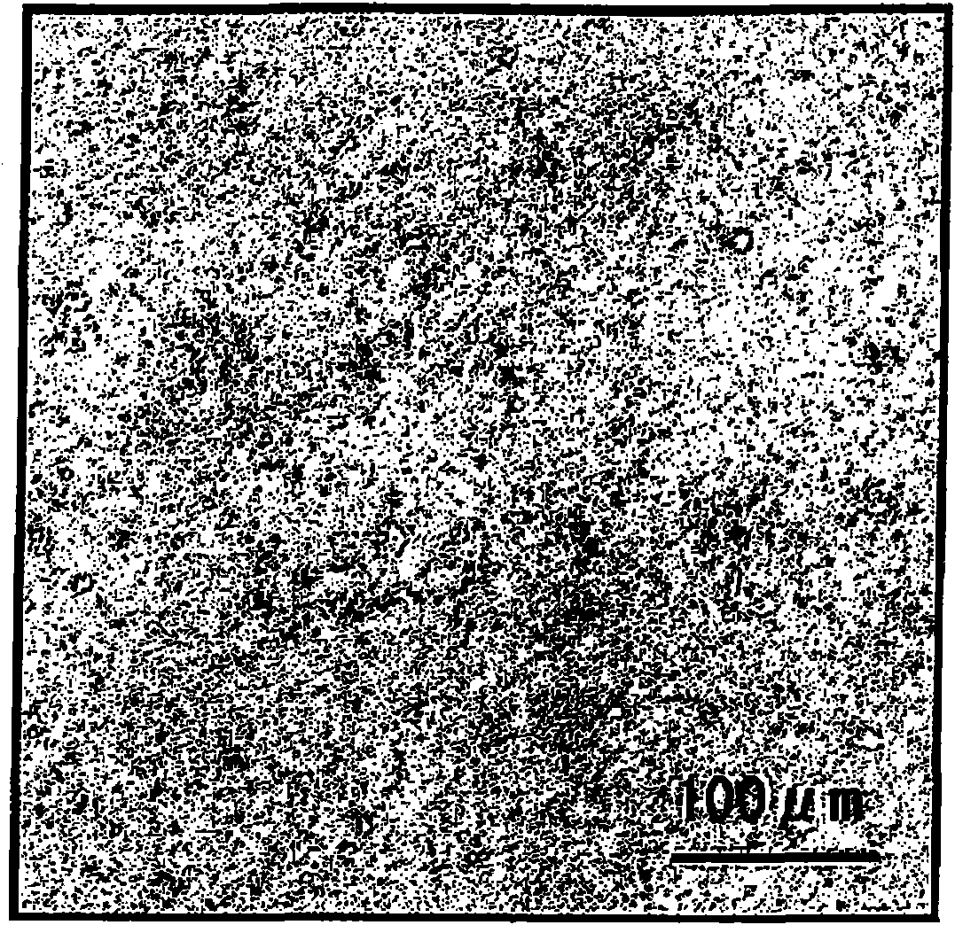
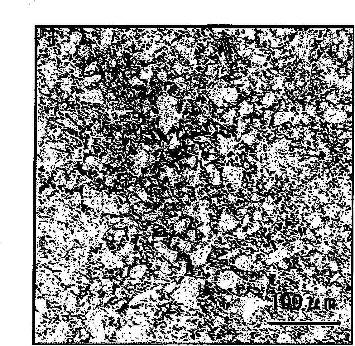
  • Thermo-electric converting materials, process for producing the same, and thermo-electric converting element
  • Thermo-electric converting materials, process for producing the same, and thermo-electric converting element
  • Thermo-electric converting materials, process for producing the same, and thermo-electric converting element

Examples


Embodiment 1

[0225] The silicon residue discharged and generated during the dicing process of the semiconductor assembly of the semiconductor manufacturing company was filtered and separated using a recovery device (manufactured by Sanyo Electric Co., Ltd., Aquacro-Za) and a filter press (manufactured by Parker Engineering Co., Ltd.), and the silicon concentration was obtained. As a result of analysis, the grade (3) silicon residue with a water content of 95% by mass and a water content of 5% by mass was confirmed to contain a B concentration of 100 ppm and a P concentration of 1000 ppm.

[0226] Then, transfer to the dehydration treatment step in the purification and refining step, after throwing the above-mentioned (3) grade silicon residue into a commercially available electric furnace, while supplying argon gas containing 5 vol % hydrogen at a flow rate of 3000 l / min, in the atmosphere The temperature was set at 250° C., and heat treatment was performed for 3 hours to remove moisture. ...

Embodiment 2

[0246] Filter and separate silicon residues discharged and generated during wafer processing (mirror grinding and back grinding processes) at semiconductor manufacturing companies to obtain residues with a silicon concentration of 92% by mass and a moisture content of 8% by mass, and confirm the analysis results , is a grade (2) silicon residue with a B concentration of 6 ppm and a P concentration of 70 ppm.

[0247] A sintered body (undoped) was obtained in the same manner as in Example 1 except that the obtained silicon residue was used and a sintering pressure of 30 MPa was used.

[0248] The obtained sintered body was analyzed in the same manner as in Example 1, and as a result, it contained 90 ppm of Al-derived 2 o 3 Al, 240ppm As, 8ppm P, and 4ppm B are used to make crucibles.

[0249] The density of the obtained sintered body was 99% of the theoretical density.

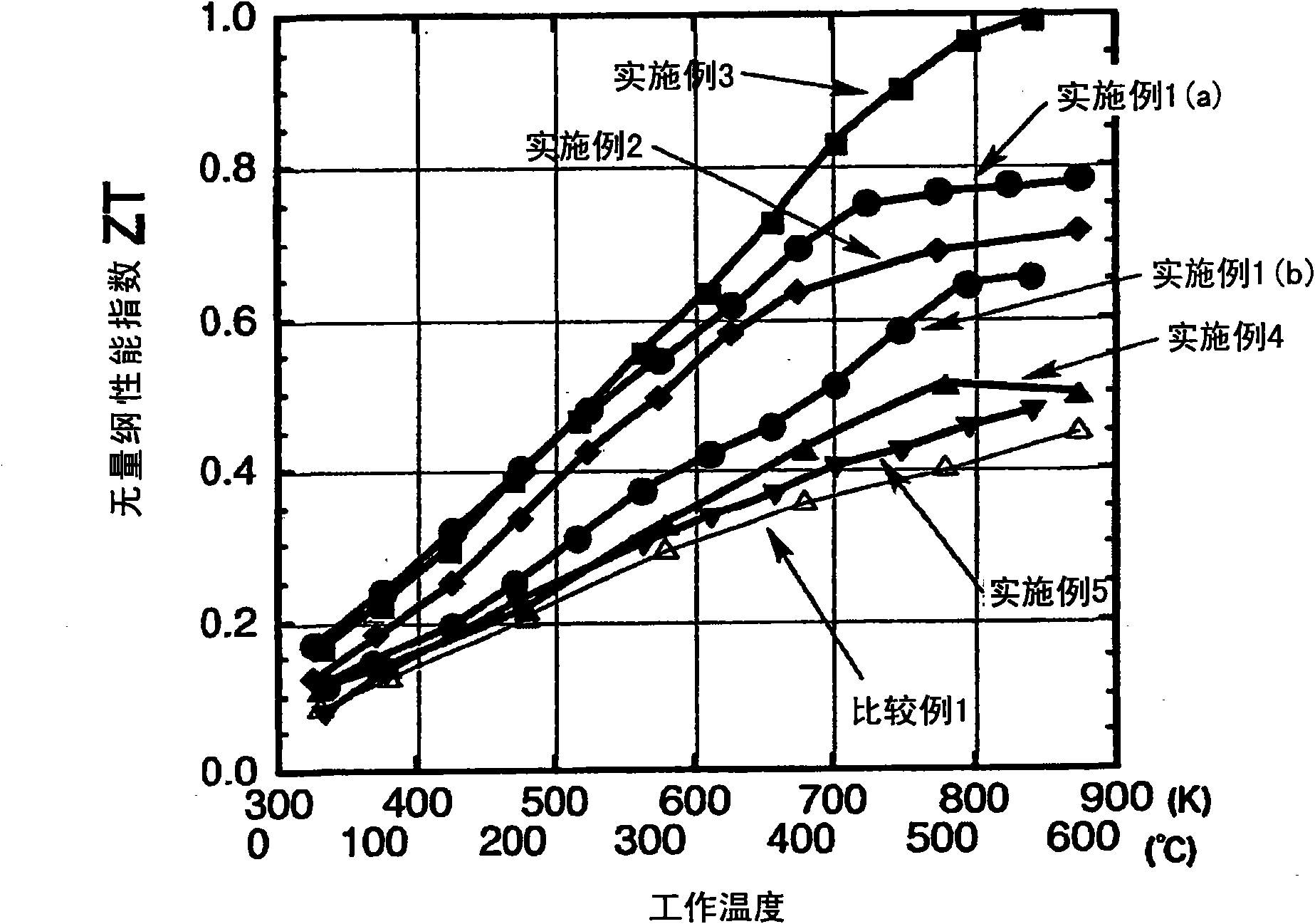
[0250] Using the obtained sintered body, the dimensionless performance index ZT was calculated in the sam...

Embodiment 3

[0253] The silicon residues discharged and generated during wafer processing (mirror grinding and back grinding processes) in semiconductor manufacturing companies were filtered and separated to obtain residues with a silicon concentration of 92% by mass and a water content of 8% by mass. Analysis results It was confirmed that it was a grade (2) silicon residue with a B concentration of 6 ppm and a P concentration of 70 ppm.

[0254] Then, transfer to the dehydration treatment step in the purification step, use a commercially available electric furnace, while supplying argon gas containing 5 volume % hydrogen at 3000 l / min, set the temperature at 250° C. in the atmosphere, and heat-treat the silicon residue for 3 hours, the moisture was removed.

[0255] Thereafter, transfer to the silicon oxide removal step in the purification and refining step, the above-mentioned silicon residue that has been dehydrated is fed in the same above-mentioned electric furnace while supplying arg...


PUM

PropertyMeasurementUnit
particle sizeaaaaaaaaaa
diameteraaaaaaaaaa

Abstract

A thermo-electric converting material which can stably have high thermo-electric converting performances at about 300-600 DEG C, has high physical strength, does not weather, and has excellent durability. It has high stability and high reliability. Also provided are a process for producing the material and a thermo-electric converting element. Furthermore provided is a thermo-electric converting material obtained from raw materials including a silicon sludge, which has had no uses except for landfill disposal. thermo-electric converting materials are characterized by including, as a major component, a sinter made of magnesium silicide of a polycrystalline structure containing at least one element selected among arsenic, antimony, phosphorus, aluminum, and boron. In the production process, a silicon sludge which has undergone a purification treatment is used.

Description

technical field [0001] The present invention relates to a thermoelectric conversion material, a manufacturing method thereof, and a thermoelectric conversion element. Background technique [0002] In the past, the waste silicon residue discharged when grinding and grinding silicon ingots and silicon wafers made of high-purity silicon used in the manufacture of silicon products such as semiconductors and solar cells is very fine, with a particle size of 0.1 to 10 μm, and In addition to silicon, it also contains boron, phosphorus, tungsten, chromium, titanium, arsenic, gallium, iron, oxygen, etc., which are implanted into the wafer surface in the form of impurities by ion implantation. When adding polyaluminum chloride or aluminum sulfate as a flocculant. [0003] In addition, water can be used to improve lubricity at the time of grinding and grinding. However, since oil and the like are added to the water, many impurities represented by oil and the like are contained in the ...

Claims


Application Information

Patent Timeline
Patent Type & Authority Applications(China)
IPC IPC(8): H01L35/20C02F11/00C02F11/12C04B35/00C04B35/58H01L35/34
CPCC04B2235/81C04B2235/5445C04B35/6261C04B35/6263H01L35/34C04B2235/666C04B35/6268C04B2235/40C04B2235/79C04B35/58085C04B2235/77C04B35/6455C04B2235/725C04B2235/652C04B35/62655C04B2235/402C04B2235/401B09B3/005C04B2235/42C04B2235/727C04B2235/428C04B2235/72C04B35/6265C04B35/645C04B2235/6581C04B35/62665C04B2235/5427C04B35/62204C04B2235/5436C04B2235/421H01L35/22Y02W10/37B09B3/29H10N10/855H10N10/01C02F11/00C04B35/00C04B35/58H10N10/854
Inventor 饭田努水户洋彦根本崇
Owner SHOWA KDE
Why Eureka
Eureka Blog
Learn More