
High-alloy centrifugal compound cast steel supporting roll and manufacturing technology thereof

A technology of centrifugal composite and backup rolls, which is applied in manufacturing tools, metal rolling, metal rolling, etc., can solve the problems of reduced production efficiency, short service life, large economic burden on enterprises, etc., so as to improve the work yield and service life. The effect of improving and anti-accident performance

Active Publication Date: 2009-07-15
TANGSHAN XIANLONG ROLL INDAL
View PDF0 Cites 23 Cited by
  • Summary
  • Abstract
  • Description
  • Claims
  • Application Information

AI Technical Summary

Problems solved by technology

When these backup rolls are used online, there are common destructive failure forms such as shoulder off, spalling, cracks, and roll breakage, resulting in increased roll consumption and reduced production efficiency.
The reason for these phenomena is that the metallographic structure of these back-up roll materials is characterized by the presence of a large amount of M in the metallographic structure 3 C-type carbide, the matrix is ​​generally pearlite or tempered sorbite depending on the heat treatment system. This metallographic structure has poor mechanical properties and high brittleness, and its mechanical properties and contact fatigue resistance cannot meet the needs of backup rolls. The technical requirements, in the process of use can not resist the strong rolling force, the service life is short
Moreover, the existing backup roll manufacturing process adopts vertical centrifugal casting, which requires large equipment investment and low process yield, which brings a large economic burden to the enterprise.

Method used


Image

  • High-alloy centrifugal compound cast steel supporting roll and manufacturing technology thereof
  • High-alloy centrifugal compound cast steel supporting roll and manufacturing technology thereof

Examples


Embodiment 1

[0026] Example 1: According to the composition of the working layer of the high-alloy centrifugal composite cast steel backup roll, put the proportioned scrap steel into the induction furnace for smelting, analyze the chemical substances of the original molten steel after melting, and then add the corresponding alloy raw materials according to the process, and smelt to obtain chemical Composition: Working layer: C 0.40%, S 0.025%, Si 0.46%, Mn 0.40%, P 0.030%, Ni 0.20%, Cr 4.50%, Mo 0.35%, and the rest is scrap steel and impurities in the working layer molten steel (the scrap steel is 93.36 %, impurity is 0.05%), core: C 3.00%, S 0.008%, Si 2.00%, Mn 0.20%, P 0.050%, Ni 0.20%, Cr 1.00%, Mo 0.50%, Re 0.040%, Mg 0.03% , the rest is molten iron with iron and impurities (including 45% pig iron, 20% steel scrap, 27.99% recycled materials, and 0.012% impurities), centrifugally cast high-alloy centrifugal composite cast steel backup rolls, and the tapping temperature of the working la...

Embodiment 2

[0027] Example 2: According to the composition of the working layer of the high-alloy centrifugal composite cast steel backup roll, put the proportioned scrap steel into the induction furnace for smelting, analyze the chemical substances of the original molten steel after melting, and then add the corresponding alloy raw materials according to the process, and smelt to obtain chemical Composition: Working layer: C 0.45%, S 0.020%, Si 0.30%, Mn 0.62%, P 0.025%, Ni 0.60%, Cr 4.00%, Mo 0.20%, and the rest is scrap steel and impurities in the working layer molten steel (the proportion of scrap steel 93.75%, impurity proportion 0.035%, core: C 3.60%, S 0.003%, Si 1.70%, Mn 0.63%, P 0.069%, Ni 0.50%, Cr 0.55%, Mo 0.10%, Re 0.02%, Mg 0.055 %The rest is molten iron of iron and impurities (wherein pig iron accounts for 46%, steel scrap accounts for 22.5%, returned material accounts for 24.22%, and impurities account for 0.053%). Centrifugally cast high-alloy centrifugal composite cast s...

Embodiment 3

[0028] Example 3: According to the composition of the working layer of the high-alloy centrifugal composite cast steel backup roll, put the proportioned scrap steel into the induction furnace for melting, analyze the chemical substances of the original molten steel after melting, and then add the corresponding alloy raw materials according to the process, and melt to obtain chemical Composition: Working layer: C 0.50%, S 0.028%, Si 0.60%, Mn 0.80%, P 0.034%, Ni 1.00%, Cr 3.50%, Mo 0.50%, and the rest is scrap steel and impurities in the working layer molten steel, (of which scrap steel accounts for Specific gravity 93%, impurity proportion 0.038%) Core: C 3.60%, S 0.005%, Si 2.70%, Mn 1.00%, P 0.045%, Ni 0.80%, Cr 0.20%, Mo 1.00%, Re 0.010%, Mg The rest of 0.08% is molten iron of iron and impurities (wherein pig iron accounts for 44%, steel scrap accounts for 20.8%, recycled material accounts for 25.73%, and impurities account for 0.03%). Centrifugal casting of high-alloy cent...


PUM


Abstract

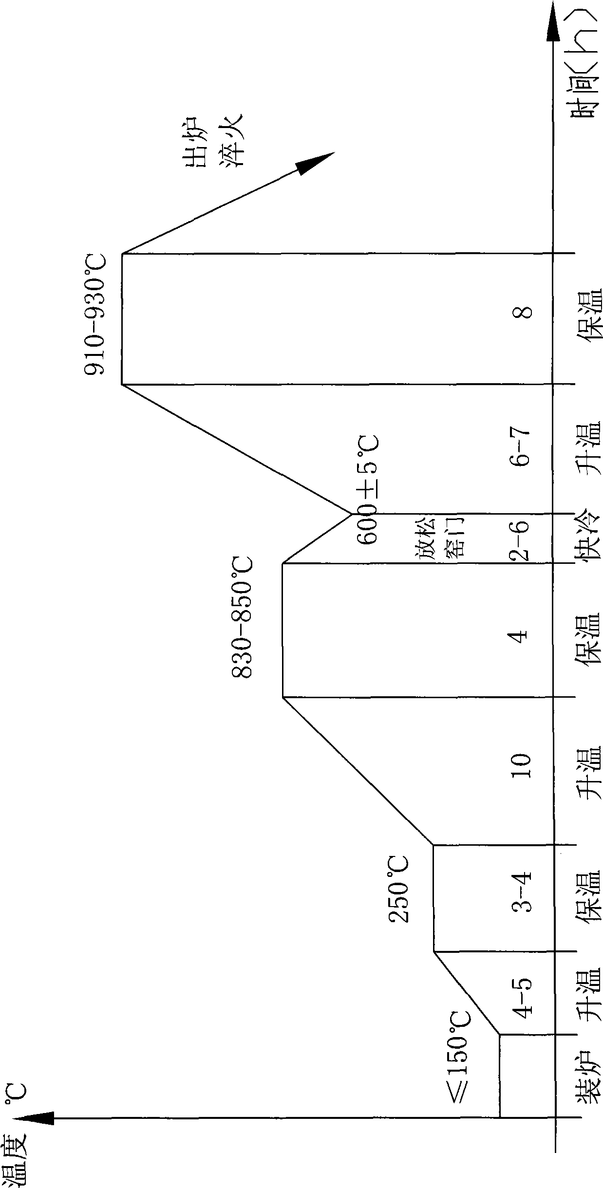
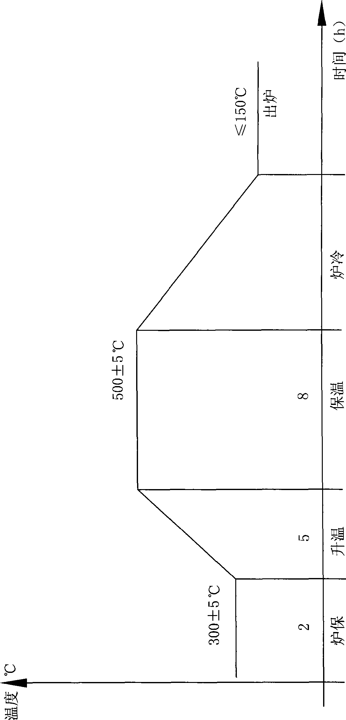
The invention relates to a high-alloy centrifugal compounding steelcasting support roll and a processing technique thereof. The high-alloy centrifugal compounding steelcasting support roll comprises the following chemical substances: a working layer containing 0.4-0.5 of C, 0.3-0.6 of Si, 0.4-0.8 of Mn, less than or equal to 0.035 of P, less than or equal to 0.03 of S, 3.5-4.5 of Cr, 0.2-1.0 of Ni and 0.2-0.5 of Mo, and the balance steel and impurities by weight; a core part containing 3.0-3.6 of C, 1.7-2.7 of Si, 0.2-1.0 of Mn, less than or equal to 0.08 of P, less than or equal to 0.01 of S, 0.01-0.04 of Re, 0.03-0.08 of Mg, less than or equal to 1.0 of Cr, less than or equal to 1.0 of Ni, less than or equal to 1.0of Mo, less than or equal to 1.0 of Cu, less than or equal to1.0 of V, and the balance iron and impurities by weight. Furthermore, the working layer is formed by horizontal type centrifugal pouring, the core part is formed by pouring, and the heat treatment is carried out in such a way that a trolley type high-temperature resistance furnace to heat a rough machining support roll in an austenite way and preserve the heat of the rough machining support roll. The invention has high abrasion resistance, high accident prevention and high working production ratio.

Description

technical field [0001] The invention relates to a backup roll used in wide-band, medium-wide-band and narrow-band continuous rolling mills and a manufacturing method of the backup roll, in particular to a high-alloy centrifugal composite cast steel backup roll and its manufacturing process. Background technique [0002] At present, the back-up rolls of wide-band and medium-broad continuous rolling mills are usually cast with alloy semi-steel materials, or remanufactured from scrapped integral forged steel rolls; the back-up rolls of narrow-band continuous rolling mills are generally made of alloy semi-steel composite casting. When these backup rolls are used online, there are generally destructive failure forms such as shoulder off, spalling, cracks, and broken rolls, resulting in increased roll consumption and reduced production efficiency. The reason for these phenomena is that the metallographic structure of these back-up roll materials is characterized by the presence of...

Claims


Application Information

Patent Timeline
IPC IPC(8): B21B27/02B22D13/12C21D1/20
CPCY02P10/20
Inventor 倪爱文
Owner TANGSHAN XIANLONG ROLL INDAL
Learn More