Method and system for high-speed, high-resolution, 3-D imaging of an object at a vision station

a vision station and high-resolution technology, applied in the field of high-speed, high-resolution, 3d imaging of objects at a vision station, can solve the problems of low speed (typically 10,000 points/second), severe trade-off between shadows, light sensitivity and field of view, and rarely found two-dimensional problems. achieve the effect of high speed and sensitivity

Inactive Publication Date: 2000-02-08
ELECTRO SCI IND INC
View PDF11 Cites 33 Cited by
  • Summary
  • Abstract
  • Description
  • Claims
  • Application Information

AI Technical Summary

Benefits of technology

An object of the present invention is to provide an improved method and system for high speed, high resolution 3-D imaging of an object at a vision station wherein high speed and sensitivity can be obtained by using a flying spot laser scanner with a light deflector and an optical system to deliver the light reflected from an object to a single, small area position detector such as a photodetector to develop dimensional information associated with the object while substantially reducing ambient and multiple reflected light.
Another object of the present invention is to provide a triangulation-based method and system for imaging an object at a vision station which overcomes many of the limitations of the prior art methods and systems by achieving excellent height resolution at a narrow triangulation angle wherein shadow and occlusion effects are reduced while having a relatively large field of view.
Yet still another object of the present invention is to provide a method and system for high speed imaging of an object at a vision station to develop high resolution, dimensional information associated with the object and having a high signal-to-noise ratio in a relatively inexpensive and compact fashion and which system can be interfaced with standard, high speed apparatus.
Still, preferably, the field of view of the filtered light signal is translated across the position detector by translation means to expand the range of dimensional information associated with the object.
Also, such a method and system provide high resolution, quasi-video rate, full 3-D imaging at a relatively low cost. A long scan line (i.e. field of view) is achieved as well as a high signal-to-noise ratio, height sensitivity and light gathering capability and low capacitance and "dark current".
The present invention overcomes many of the problems of the prior art by utilizing an anamorphic magnification and field lens system to deliver light to small area position sensor in conjunction with the benefits of utilizing an all solid state light deflection system (i.e. compact, rugged, easy to interface with, etc.)

Problems solved by technology

In fact, most problems in vision are 3-D in nature and two-dimensional problems are rarely found.
With linear arrays or area cameras there is severe trade off between shadows, light sensitivity and field of view.
The primary disadvantages of such a system are the very low speeds (typically 10,000 points / second) and, in the case of multiple projected lines in a single image, ambiguous interpretations of the data result from overlap of adjacent stripes and multiple scattered light between stripes.
The large area detectors have several limitations: low speed due to large detector capacitance, high dark currents, and a much higher noise floor than what is found with small area devices.
With typical triangulation-based images it is difficult to deliver light to a small area device without decreasing the field of view (and consequently the inspection speed).
These are severe limitations and impose undesirable trade-offs which limit the system performance.
These moving parts are often not desirable, particularly if the sensor is to be subjected to the type of acceleration found with x-y tables and robotic arms in industrial environments.
A dilemma exists with conventional triangulation imagers: it is desirable to use a small detector but unless moving parts are included the field of view becomes too small, the resolution too coarse, and the light gathering capability poor.
Even if the coarse resolution is tolerable, the loss of light gathering capability also further reduces the system signal-to-noise ratio The signal-to-noise ratio is not good in the first place (particularly at high speeds) because of the use of the large area detector thereby compounding the problem.
The measurement rate is slow due to the readout of the video camera.
The speed of the system is limited by the retrace time of the scanning device at each measurement point.
This method is relatively slow especially for the requirements of small part inspection at quasi-video rates (i.e. MHz).
However, the method is deficient for several other types of inspection tasks because (1) unacceptable shadows and occlusion effects would occur for tall objects; (2) the field of view of the probe is very small; (3) a reduction of the angle to 15 degrees (to reduce shadows) would degrade the height sensitivity significantly; and (4) the detector area is relatively large which limits speed and the signal to noise ratio as the speed of the system is increased.
Again, the speed and stray light rejection capabilities of the probe are limited which restrict it to depth measurement of objects (like traces) which are not very tall.
.Iadd.bi-cell.Iaddend., however, does not compute the centroid of the received light spot and is therefore sensitive to the distribution of intensity within the received light spot.

Method used


Image

  • Method and system for high-speed, high-resolution, 3-D imaging of an object at a vision station
  • Method and system for high-speed, high-resolution, 3-D imaging of an object at a vision station
  • Method and system for high-speed, high-resolution, 3-D imaging of an object at a vision station

Examples


Embodiment Construction

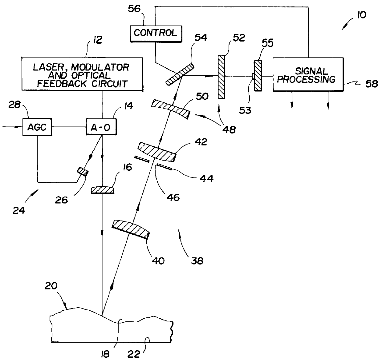
Referring now to FIG. 1, there are illustrated the major components of a 3-D imaging system constructed in accordance with the present invention and generally indicated at 10. The system 10 is positioned at a vision station and includes a controlled source of light such as a laser, modulator and optical feedback circuit 12. A scanner in the form of an acousto-optic deflector 14 and beam shaping and focusing optics in the form of various lens elements 16 produce a telecentric, flat field scan by projecting a series of laser beams at the reflective surface 18 of an object, generally indicated at 20. The object is supported on a reference, planar surface 22 at the vision station.

Within the block 12 a laser is coupled to a modulator to shift the information to a higher frequency where system noise characteristics are better. The modulator may perform one of many types of modulation, including sine wave, pulse amplitude, pulse position, etc. Preferably, the laser is a solid state laser d...


PUM


Abstract

A method and system for high-speed, high-resolution, 3-D imaging of an object including an anamorphic magnification and field lens system to deliver the light reflected from the object to a small area position detector having a position-sensing direction. Preferably, an acousto-optic deflector together with associated lens elements scans a beam of modulated laser light across the object to produce a telecentric, flat field scan. The deflector has a feedback loop to enable uniform illumination of the object. The light scattered from the object is collected by a telecentric receiver lens. A combined spatial and polarization filtering plane preferably in the form of a programmable mask is provided to control the polarization and acceptance angles of the collected light. A reduction or focusing lens is positioned immediately behind the filtering plane and is utilized as a telescope objective. The lens system includes a negative cylinder lens having a relatively large focal length and a field lens having a relatively small focal length. The cylinder lens and the reduction lens magnify the image in the position sensing direction of the detector and the field lens delivers the magnified light to the detector. The detector is a photodetector such as a lateral effect photodiode or a rectangular lateral effect detector. A pre-amplifier provides a pair of electrical signals which are utilized by signal processing circuitry to compute the centroid of the light spot.

Description

TECHNICAL FIELDThis invention relates to a method and system for imaging an object at a vision station to develop dimensional information associated with the object and, in particular to a method and system for the high-speed, high resolution imaging of an object at a vision station to develop dimensional information associated with the object by projecting a beam of controlled light at the object.BACKGROUND ARTA high-speed, high resolution (i.e. approximately 1 mil and finer) 3-D laser scanning system for inspecting miniature objects such as circuit board components, solder, leads and pins, wires, machine tool inserts, etc., can greatly improve the capabilities of machine vision systems. In fact, most problems in vision are 3-D in nature and two-dimensional problems are rarely found.Several methods have been used to acquire 3-D data: time of flight, phase detection, autofocus, passive stereo, texture gradients, or triangulation. The latter approach is well suited for high resolutio...

Claims


Application Information

Patent Timeline
IPC IPC(8): G01B11/24G01B11/02G01B11/00
CPCG01B11/02G01B11/24
Inventor SVETKOFF, DONALD J.DOSS, BRIAN L.
Owner ELECTRO SCI IND INC
Why Eureka
Try Eureka