
Method, system and apparatus for dark-field reflection-mode photoacoustic tomography

a technology of photoacoustic tomography and dark field reflection, applied in the field of laser photoacoustic imaging system, to achieve the effect of high image resolution, high sensitivity and high resolution

Inactive Publication Date: 2006-08-17
TEXAS A&M UNIVERSITY
View PDF19 Cites 284 Cited by
  • Summary
  • Abstract
  • Description
  • Claims
  • Application Information

AI Technical Summary

Benefits of technology

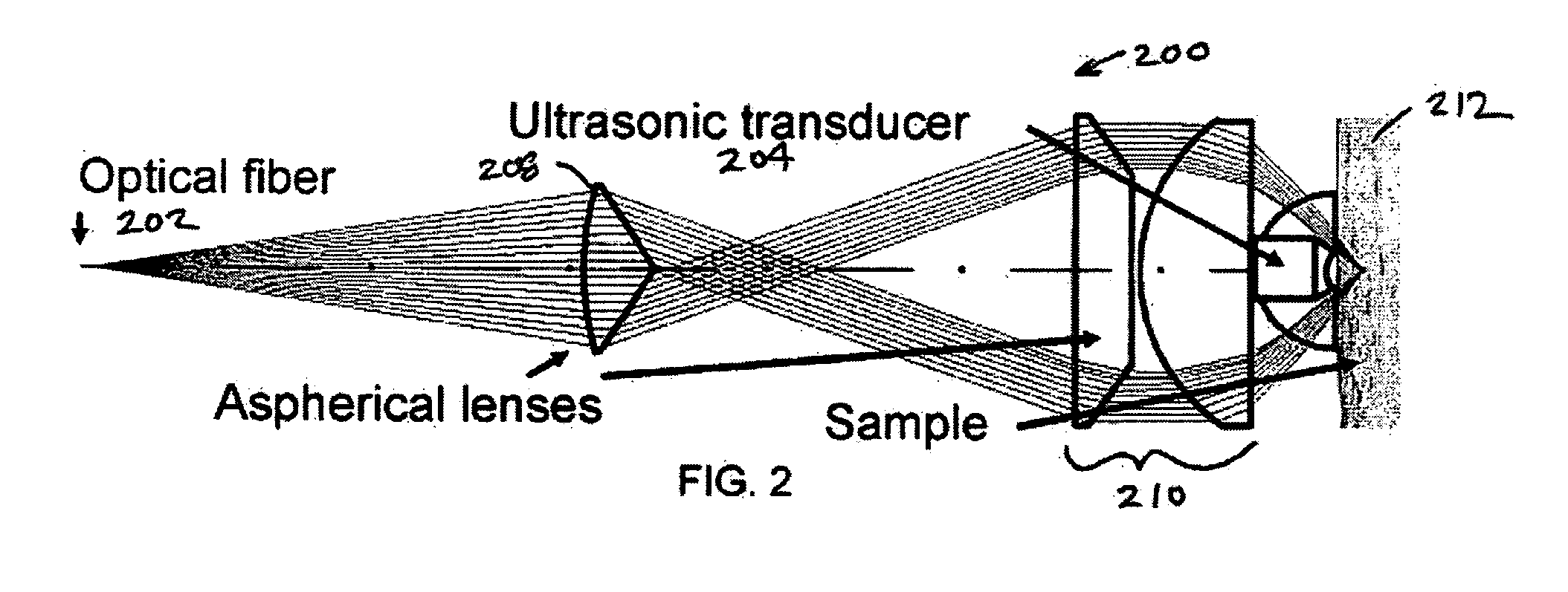
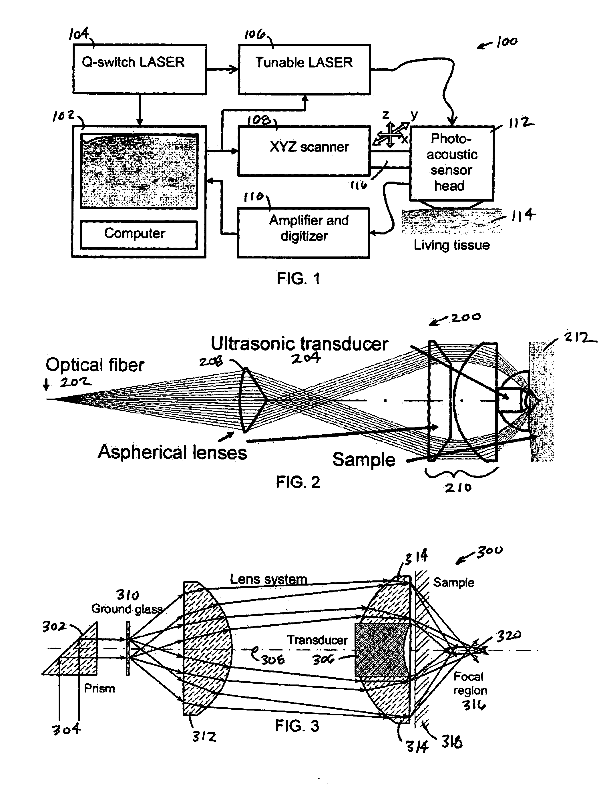
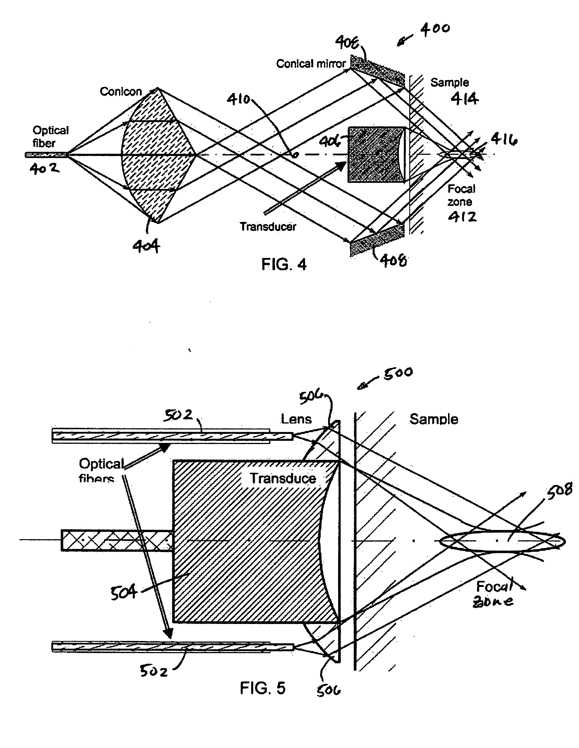
The present invention provides a method, system, and apparatus for reflection-mode microscopic photoacoustic imaging using dark-field illumination and a large numerical-aperture spherically focused ultrasonic transducer. This technique improves the imaging of relatively deep subsurface tissue structures with high resolution and sensitivity. The invention uses a laser to illuminate the tissue and an ultrasonic transducer to receive the acoustic or pressure waves induced by the laser. The received signals are processed to obtain the three-dimensional distribution of optical contrast within the sample volume. The invention has advantages over existing bright-field illumination systems and can be used for diagnostic, treatment, and research purposes. It can be incorporated into a system that includes a pulsed laser and an electronic system that records and processes the received acoustic or pressure waves. The invention can be used in the diagnosis and monitoring of various tissue abnormalities and can provide quantitative information about tissue function and structure. It can also be used to monitor changes in tissue caused by treatment or cosmetics application.

Problems solved by technology

Secondly, the large illumination area partially averages out the shadows of superficial heterogeneity in the image.

Method used


Image

  • Method, system and apparatus for dark-field reflection-mode photoacoustic tomography
  • Method, system and apparatus for dark-field reflection-mode photoacoustic tomography
  • Method, system and apparatus for dark-field reflection-mode photoacoustic tomography

Examples


Embodiment Construction

[0035] While the making and using of various embodiments of the present invention are discussed in detail below, it should be appreciated that the present invention provides many applicable inventive concepts that can be embodied in a wide variety of specific contexts. The specific embodiments discussed herein are merely illustrative of specific ways to make and use the invention and do not delimit the scope of the invention.

[0036] To facilitate the understanding of this invention, a number of terms are defined below. Terms defined herein have meanings as commonly understood by a person of ordinary skill in the areas relevant to the present invention. Terms such as “a,”“an” and “the” are not intended to refer to only a singular entity, but include the general class of which a specific example may be used for illustration. The terminology herein is used to describe specific embodiments of the invention, but their usage does not delimit the invention, except as outlined in the claims...


PUM


Abstract

The present invention provides a method, system and apparatus for reflection-mode microscopic photoacoustic imaging using dark-field illumination that can be used to characterize a target within a tissue by focusing one or more laser pulses onto a surface of the tissue so as to penetrate the tissue and illuminate the target, receiving acoustic or pressure waves induced in the target by the one or more laser pulses using one or more ultrasonic transducers that are focused on the target and recording the received acoustic or pressure waves so that a characterization of the target can be obtained. The target characterization may include an image, a composition or a structure of the target. The one or more laser pulses are focused with an optical assembly of lenses and / or mirrors that expands and then converges the one or more laser pulses towards the focal point of the ultrasonic transducer.

Description

CROSS-REFERENCE TO RELATED APPLICATIONS [0001] This application claims priority to U.S. Provisional Application Ser. No. 60 / 646,351, filed Jan. 22, 2005, the contents of which are incorporated by reference herein in their entireties.TECHNICAL FIELD OF THE INVENTION [0002] The present invention relates generally to the fields of optics, lasers and medical diagnostic devices. More specifically, the present invention relates to a laser photoacoustic imaging system capable of producing a three-dimensional image (tomographic scan) of human organs. BACKGROUND OF THE INVENTION [0003] The U.S. Government may own certain rights in this invention pursuant to the terms of the NIH Grant Nos. R01 EB000712 and R01 NS046214. Without limiting the scope of the invention, its background is described in connection with optics, lasers and medical photoacoustic imaging systems and diagnostic devices, as an example. The ability to image the micro-vascular network in skin is invaluable in dermatology and ...

Claims


Application Information

Patent Timeline
Patent Type & Authority Applications(United States)
IPC IPC(8): A61B6/00
CPCA61B5/0068A61B5/0073A61B5/0084A61B5/0091A61B5/0095
Inventor WANG, LIHONGMASLOV, KONSTANTIN
Owner TEXAS A&M UNIVERSITY
Learn More