Eureka AIR delivers breakthrough ideas for toughest innovation challenges, trusted by R&D personnel around the world.

High dynamic range image combining

a high dynamic range, image technology, applied in image enhancement, instruments, television systems, etc., can solve the problem of not supporting the increased data requirements of the resulting hdr image, and achieve the effect of enhancing contrast images

Active Publication Date: 2010-06-24
QUALCOMM INC
View PDF22 Cites 277 Cited by
  • Summary
  • Abstract
  • Description
  • Claims
  • Application Information

AI Technical Summary

Benefits of technology

The patent describes a method for generating high dynamic range (HDR) images that have enhanced contrast and are compatible with lower dynamic range image transport and display mechanisms. The method involves receiving first image data from an image sensor and scaling the luminance values of the first image data based on a ratio of the second exposure time to the first exposure time. The second image data is generated using a second exposure time that is greater than the first exposure time. The method also involves selectively combining the scaled first image data and the second image data based on an overlap between a first effective dynamic range (EDR) and a second EDR of the second image data. The resulting HDR image is then compressed to a smaller dynamic range using a tone mapping process that determines a pixel-by-pixel weighting of a global tone mapping value and a local tone mapping value based on the luminance variation within a neighborhood of each pixel. The wireless device, apparatus, and computer readable medium described in the patent allow for the generation and use of HDR images in various applications.

Problems solved by technology

Although the resulting HDR image may provide enhanced contrast due to the combination of different images with different exposure times, many displays or data transport standards do not support the increased data requirements of the resulting HDR image.

Method used


Image

  • High dynamic range image combining
  • High dynamic range image combining
  • High dynamic range image combining

Examples


Embodiment Construction

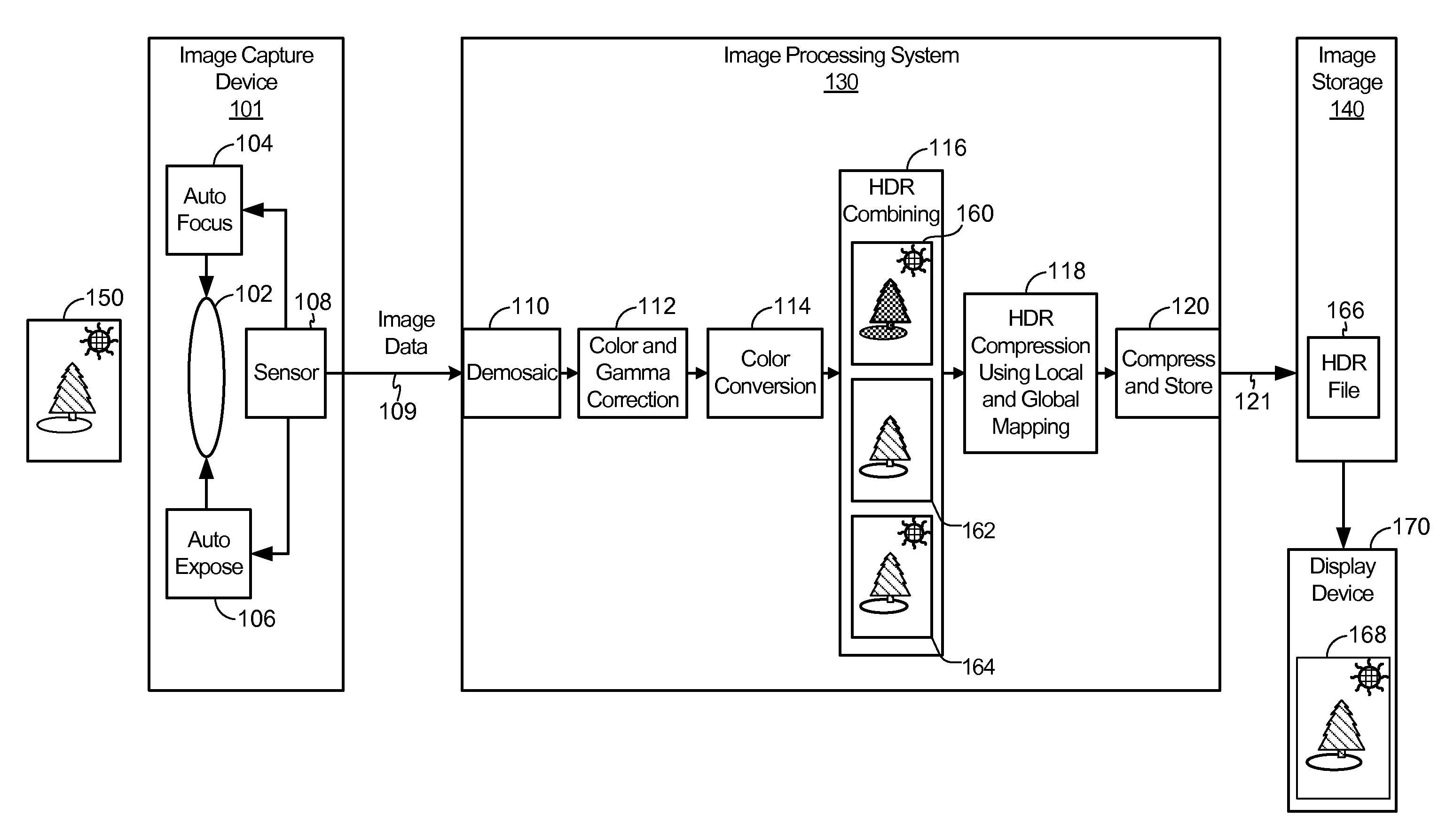
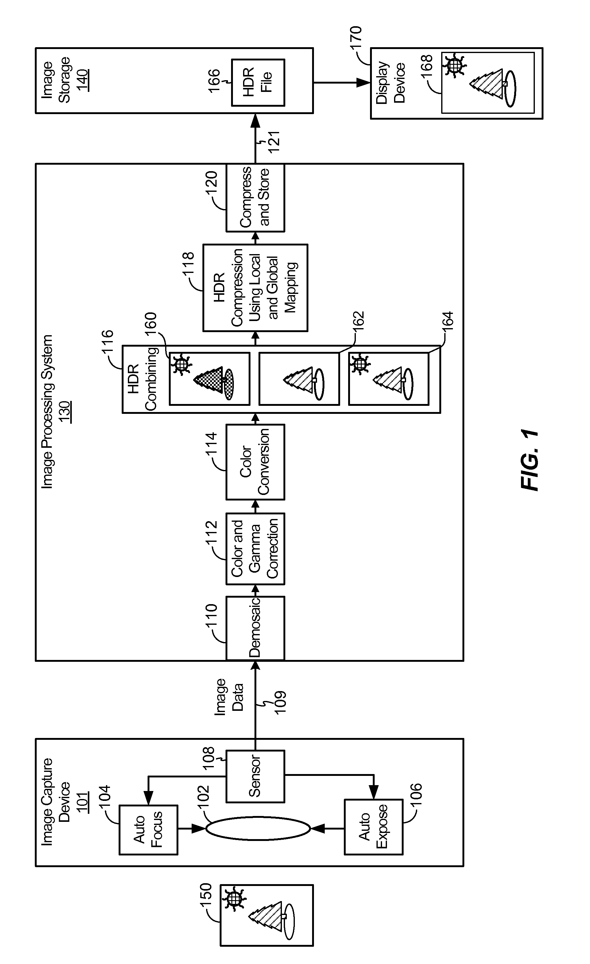
[0025]FIG. 1 is a block diagram of a particular illustrative embodiment of a system including an image processing system having a high dynamic range (HDR) combining module and a HDR compression module using local and global mapping. The system 100 includes an image capture device 101 coupled to an image processing system 130. The image processing system 130 is coupled to an image storage device 140 and a display device 170. The image processing system 130 is configured to receive multiple sets of image data 109 from the image capture device 101 using different exposure times and to create a HDR image that is compatible with low dynamic range (LDR) transport, storage, and display mechanisms. Generally, the system 100 may be implemented in an electronic device that is configured to perform real-time image processing using relatively limited processing resources.

[0026]In a particular embodiment, the image capture device 101 is a camera, such as a video camera or a still camera. The ima...


PUM


Abstract

Systems and methods of high dynamic range image combining are disclosed. In a particular embodiment, a device includes a global mapping module configured to generate first globally mapped luminance values within a region of an image, a local mapping module configured to generate second locally mapped luminance values within the region of the image, and a combination module configured to determine luminance values within a corresponding region of an output image using a weighted sum of the first globally mapped luminance values and the second locally mapped luminance values. A weight of the weighted sum is at least partially based on a luminance variation within the region of the image.

Description

I. FIELD [0001]The present disclosure is generally related to high dynamic range image combining.II. DESCRIPTION OF RELATED ART [0002]Advances in technology have resulted in smaller and more powerful computing devices. For example, there currently exist a variety of portable personal computing devices, including wireless computing devices, such as portable wireless telephones, personal digital assistants (PDAs), and paging devices that are small, lightweight, and easily carried by users. More specifically, portable wireless telephones, such as cellular telephones and internet protocol (IP) telephones, can communicate voice and data packets over wireless networks. Further, many such wireless telephones include other types of devices that are incorporated therein. For example, a wireless telephone can also include a digital still camera, a digital video camera, a digital recorder, and an audio file player. Also, such wireless telephones can process executable instructions, including s...

Claims


Application Information

Patent Timeline
Patent Type & Authority Applications(United States)
IPC IPC(8): H04N5/228H04N23/40
CPCG06T5/007G06T5/40G06T5/50G06T2207/20221G06T2207/20004G06T2207/20012G06T2207/10144G06T5/90H04N5/262G06T3/00
Inventor ATANASSOV, KALIN M.VELARDE, RUBEN M.LI, HSIANG-TSUNHWANG, HAU
Owner QUALCOMM INC
Why Eureka
Eureka Blog
Learn More