
Process and apparatus for production of halogenated butyl rubber with reduced emissions

a technology of halogenated butyl rubber and process, which is applied in the direction of chemical/physical/physical/physical-chemical process, chemical/physical/physical-chemical stationary reactor, chemical/physical/physical-chemical reactor details, etc. it can solve the problems of process and mechanical reliability problems, limitations of the process disclosed, and the existing system is not suitable for use with certain non-halogenated organic solvents having a lower boiling point than hexane, etc. problems, to achieve the effect o

Active Publication Date: 2017-05-09
ARLANXEO DEUT GMBH
View PDF7 Cites 7 Cited by
  • Summary
  • Abstract
  • Description
  • Claims
  • Application Information

AI Technical Summary

Benefits of technology

This approach enables the continuous production of halogenated butyl rubber with reduced solvent emissions and improved mechanical reliability, allowing for a wider range of organic solvents and rubber concentrations, while maintaining efficient phase separation and minimizing emulsion formation.

Problems solved by technology

There are several disadvantages associated with such a cement forming process, for example, the commonly used surge drums are open to the atmosphere, the rotary valve on the pre-dissolving drum is a significant source of hexane emissions, the dewatering screens and rotary valve may have process and mechanical reliability issues, and more importantly, the existing system is not suitable for use with certain non-halogenated organic solvents having a lower boiling point than hexane, such as isopentane or n-pentane, due to excessive emissions.
However, there are several limitations to the process disclosed.
Secondly, it refers to a commercially impractical range of 3-5% aqueous dispersion of butyl rubber.
Thirdly, it discloses a vertical mixing vessel and a vertical separator configuration, which may be detrimental to the phase separation by not providing adequate interface area and / or forming a difficult to separate emulsion.

Method used


Image

  • Process and apparatus for production of halogenated butyl rubber with reduced emissions
  • Process and apparatus for production of halogenated butyl rubber with reduced emissions
  • Process and apparatus for production of halogenated butyl rubber with reduced emissions

Examples


example 1

Laboratory Batch Experiments

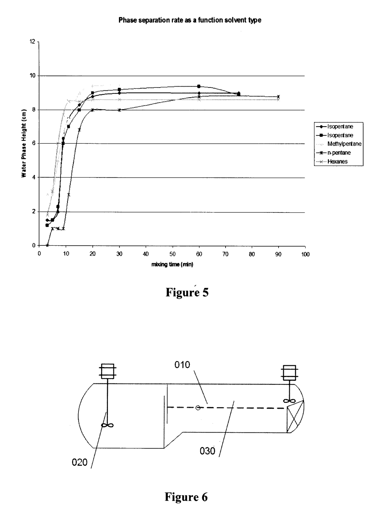
[0058]Batch experiments were carried out using a closed glass reactor apparatus to simulate plant conditions. The main variables that were investigated for their influences on the cement make up process are: agitation time; temperature (23° C., 40° C. and 65° C.); butyl rubber grades (LANXESS chlorobutyl CB1240 and bromobutyl BB2030, BB2040 and BBX2 base rubbers) rubber particle size (large crumb size: 6.3-19.9 mm, small crumb size: 0.5-3.5 mm); calcium stearate level (1% and 3%); and solvent type (hexanes, isohexane, isopentane, n-hexane).

Materials Used in this Study

[0059]Butyl rubber crumb (chlorobutyl CB1240 and bromobutyl BB2030, BB2040 & BBX2 base rubber) was used as supplied by LANXESS Inc.[0060]LANXESS bromobutyl BB2030 is a brominated isobutylene-isoprene copolymer with a bromine content of 1.8±0.2 wt-% and a Mooney viscosity (ML 1+8 @ 125° C.) of 32±4.[0061]LANXESS chlorobutyl CB1240 is chlorinated isobutylene-isoprene copolymer with a chlorine c...

example 2

Batch Trials

General Description of Procedure

[0113]A 50-L vessel equipped with 4 flat baffles and a 3-stage Viscoprop agitator was used in LANXESS Rubber plant to carry out the batch trials in order to determine the detail design dimensions of the production scale vessel.

[0114]Crumbs were collected from the rubber plant and separated from the bulk water. The amount of crumbs for one trial was weighed in the laboratory. Water, which was also taken directly from the rubber slurry from the plant, was metered into the mixing vessel manually, and then the pre-weighed amount of rubber crumbs was inserted into the mixing vessel. The agitator was started and the vessel closed. The mixing vessel was brought to the desired temperature by means of a heating jacket. After the polymerization reaction was quenched, the solvent was metered into the closed vessel in the desired amount. Through a sight glass at the side of the vessel, the flow and settling behaviour were observed. Samples were taken ...

example 3

Continuous Pilot Scale Tests

[0138]A pilot mixer / settler scaled down from the full scale design was constructed to verify the mixing and settling efficiency under continuous flow conditions. The pilot mixer / settler is composed of two mixing chamber (each has a diameter of 1200 mm) and a settling chamber with a diameter of 508 mm. The total volume of the mixing and settling section is 2920 L. The mixing chambers are equipped with agitators. A small agitator is installed at the end of the settling chamber to break any rubber mat build up. The rubber slurry and plant hexane were pumped from the main production facility to the pilot unit. The cement and water separated out of the mixer settler were pumped back to the production unit. The tests were conducted under the following conditions,[0139]Product Grade=BB2030 base polymer[0140]Slurry concentration to pilot=6 wt %[0141]Cement concentration target=20 wt %[0142]Mixing agitator speeds (A8701 and A8702) were set at 83%, i.e. 141 rpm[014...


PUM

PropertyMeasurementUnit
mol %aaaaaaaaaa
temperatureaaaaaaaaaa

Abstract

The present invention relates to a process for the production of halogenated butyl rubber and an apparatus for the production of rubber cement for use in the production of halogenated butyl rubber. The process and apparatus permit direct mixing of aqueous rubber slurry with a non-halogenated organic solvent to make a rubber cement solution. The water layer is then separated from the partially dissolved rubber cement and the cement phase is sent for halogenation. The apparatus is an enclosed vessel comprised of at least one dissolving zone and at least one separator zone. The process and apparatus advantageously employ recycle of rubber cement in order to disrupt an interface layer that forms between the water and rubber cement, to thereby improve continuously operation of the process.

Description

FIELD OF THE INVENTION[0001]The present invention relates to a process and apparatus for the production of halogenated butyl rubber. In particular, the invention relates to a process for the production of halogenated butyl rubber that utilizes a closed vessel for both the dissolution of the rubber in a non-halogenated solvent and the separation of water from the rubber. A closed loop system for recovering the solvent and maintaining a desired proportion of solvent to rubber is also provided.BACKGROUND OF THE INVENTION[0002]Poly(isobutylene-co-isoprene), or IIR, is a synthetic elastomer commonly known as butyl rubber which has been prepared since the 1940's through the random cationic copolymerization of isobutylene with small amounts of isoprene (1-2 mole %). As a result of its molecular structure, IIR possesses superior air impermeability, a high loss modulus, oxidative stability and extended fatigue resistance.[0003]Butyl rubber is understood to be a copolymer of an isoolefin and ...

Claims


Application Information

Patent Timeline
Patent Type & Authority Patents(United States)
IPC IPC(8): C08C19/14B01J19/00B01J19/18C08F8/20
CPCC08C19/14B01J19/006B01J19/18B01J19/1862C08F8/20C08F210/12B01J2219/00768B01J2219/182C08L23/28C08C19/12C08L15/02
Inventor GROEMPING, TOBIASBACH, SVENWERNER, BAECKERCHEN, WEINGUYEN, PAULALAM, KEVINWISE, ROBERT MICHAELMULDER, THOMAS
Owner ARLANXEO DEUT GMBH
Learn More