Metrology method and inspection apparatus, lithographic system and device manufacturing method
a technology of lithographic system and inspection apparatus, applied in the field of metrology methods and apparatus, can solve problems such as slow process and potentially complex apparatus
- Summary
- Abstract
- Description
- Claims
- Application Information
AI Technical Summary
Benefits of technology
Problems solved by technology
Method used
Image
Examples
second embodiment
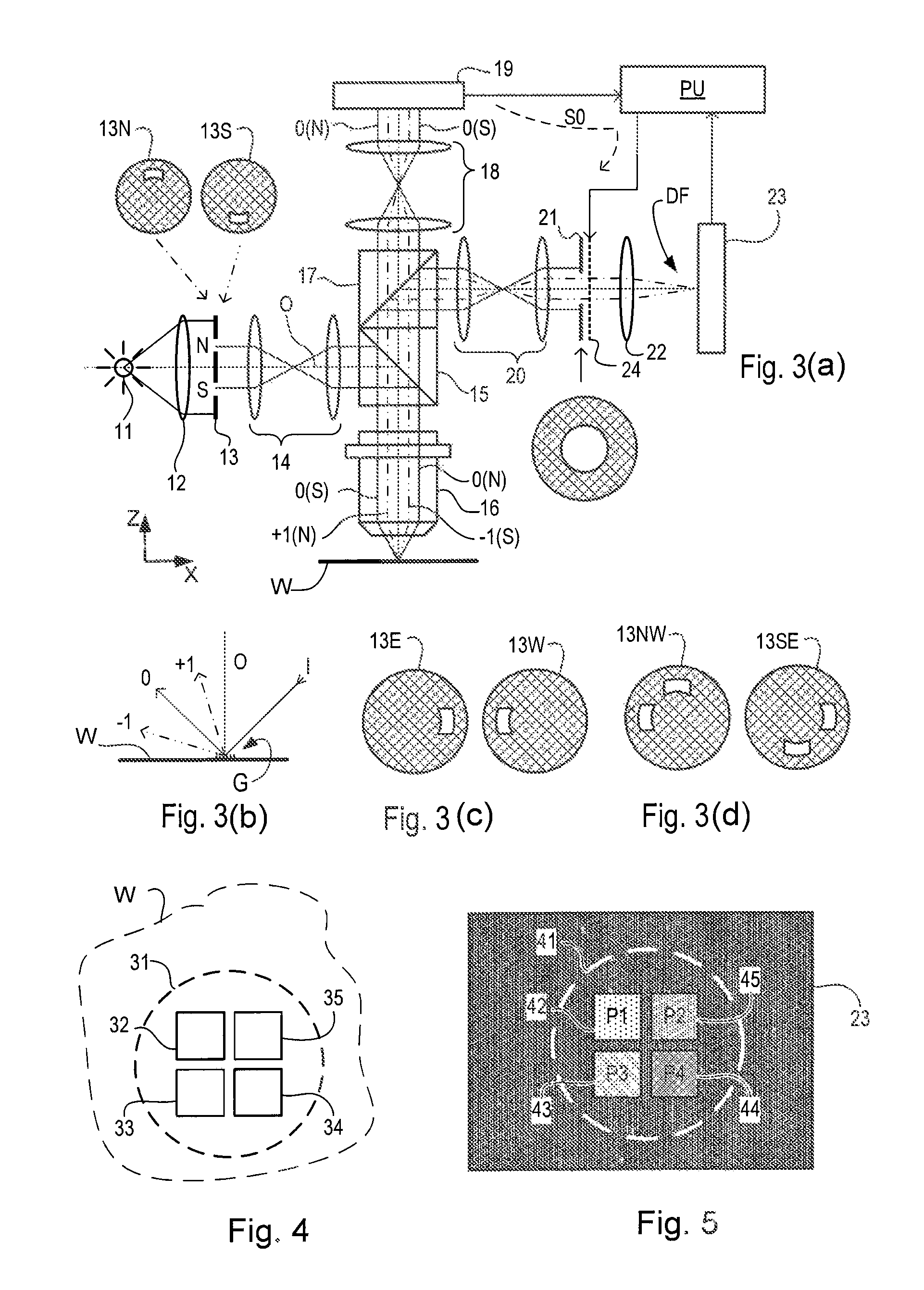
[0103]FIG. 8 illustrates a second embodiment of the invention, which is of the alternative type discussed above, which makes asymmetry measurements from dark field images taken in different imaging modes, rather than different illumination modes. A modified illumination aperture plate 113 provides on-axis illumination, just for the sake of example, while field stop 121 takes different forms to select, asymmetrically, the orders of diffracted radiation that will contribute to a dark field image on image sensor 23. Field stop 121 may, for example, take the form shown at 121N for recording the first image (step S2), being changed to the form shown at 121S, for the second measurement (step S3). Therefore, while the +1 order and −1 order beams are both shown in the diagram as chain-dotted rays extending to form a dark field image on sensor 23, only one of these rays is permitted to reach the sensor at each measurement step, the other one being blocked by field stop 121.
[0104]In this way,...
third embodiment
[0109]FIG. 10 illustrates a third embodiment. This is similar to the embodiment of FIG. 8, except that the functions of field stop and SLM have been combined in a single SLM 224. Two alternative states of SLM 224 are labeled 224N and 224S in the diagram. These different states are set up by unit PU as it controls SLM 224, to perform the functions of both the field stop having a north or south aperture, and the attenuation according to correction factors f(u,v), which were calculated for the pixel positions that happened to fall within the aperture required for each mode.
[0110]FIG. 11 illustrates at (a) and (b) how different forms of field stop 121 can be used to extend the range of targets and illumination modes for which dark field small target images can be captured. While different forms of field stop can be provided without use of an SLM, the use of the SLM allows any aperture pattern to be programmed without hardware modification, and allows aperture patterns to be switched alm...
fourth embodiment
[0115]In addition to using the SLM for correction / calibration of difference between optical paths used in different illumination and / or imaging modes, the SLM can be used to implement ‘feature extraction’ or ‘parameter extraction’ more directly from the measurements than in the methods described so far. To explain, the methods described above measure asymmetry between complementary diffraction orders (step S4), and from this asymmetry measurement and certain calibrations, another parameter such as overlay is estimated (step S5). In the fourth embodiment, the SLM is programmed with particular spatial variations in intensity that are designed so that the observed asymmetry is directly representative of a parameter of the structure being measured, or the lithographic process more generally. Such a parameter may be focus, for example. Alternatively it could be dose or an illumination parameter as far as the scanner parameters are concerned; and it can be overlay, or side wall angle as f...
PUM
| Property | Measurement | Unit |
|---|---|---|
| size | aaaaa | aaaaa |
| rotation | aaaaa | aaaaa |
| wavelength | aaaaa | aaaaa |
Abstract
Description
Claims
Application Information
 - R&D
- Intellectual Property
- Life Sciences
- Materials
- Tech Scout
- Unparalleled Data Quality
- Higher Quality Content
- 60% Fewer Hallucinations
Browse by: Latest US Patents, China's latest patents, Technical Efficacy Thesaurus, Application Domain, Technology Topic, Popular Technical Reports.
© 2025 PatSnap. All rights reserved.Legal|Privacy policy|Modern Slavery Act Transparency Statement|Sitemap|About US| Contact US: help@patsnap.com


