
In vitro point-of-care sensor and method of use

a point-of-care sensor and in vitro technology, applied in the field of in vitro sensors, can solve the problems of increasing the already high cost of care in the icu, limiting and potentially detrimental to patient safety, and positively affecting morbidity and mortality in critically ill patients

Inactive Publication Date: 2014-07-29
CASE WESTERN RESERVE UNIV
View PDF5 Cites 0 Cited by
  • Summary
  • Abstract
  • Description
  • Claims
  • Application Information

AI Technical Summary

Benefits of technology

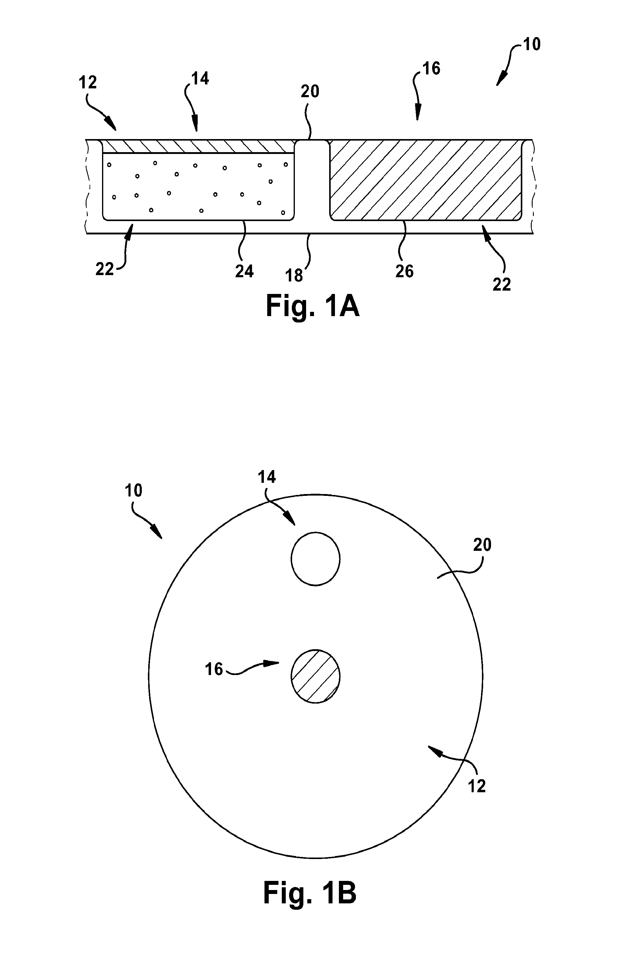
The invention is a sensor for quickly detecting substances in biological samples, such as blood or urine. It consists of a substrate, a sensing system, and a reference system. The sensing system is made up of a special membrane and a few microbeads, which are placed in a cavity in the substrate. The reference system is made up of a few microbeads, which are placed in a different cavity in the substrate. When the sensor comes into contact with a biological sample, the microbeads in the sensing system change color if they come into contact with the substance being detected. This change is easily visible to the naked eye or with a simple color reader. The sensor is designed to be used in a point-of-care setting, meaning it can be used in a physician's office or at a patient's home.

Problems solved by technology

For example, glycemic control in critically ill patients has been shown to positively impact both morbidity and mortality.
Hypoglycemia is the most common complication of using insulin infusion, while also the most limiting and potentially detrimental to patient safety.
This, along with the numerous disposable test strips required for patient care, increases the already high costs of care in the ICU.

Method used


Image

  • In vitro point-of-care sensor and method of use
  • In vitro point-of-care sensor and method of use
  • In vitro point-of-care sensor and method of use

Examples


example 1

Calibrations of HEMA-Based pH Sensors in Serum and Blood Sensor Construction

[0128]As shown in FIG. 16, a pH sensor having the following components was constructed as follows: a glass substrate (inert, transparent and impermeable); a 3-layered HEMA capsule; and white inert beads for suppressing sample optical interference layered on top of the sensing membrane. The HEMA capsule had the following configuration: a layer for attachment to the glass substrate (˜17 μm thick); a membrane capsule layer (˜150 μm thick); and a thin permeable layer for the analyte membrane and for protecting the structure against biofouling. The membrane composition had the following components as well: chromoionophore ETH350 (50 mmol); sodium ionophore Na IV (360 mmol); ionic site NaHFPB (55 mmol); and PVC:DOS (0.65).

[0129]In all cases, pH was adjusted by adding small aliquots of KOH or HCl to serum or blood.

Calibration of HEMA-Based pH Sensor in Serum

[0130]Serum calibrations for pH sensors: KOH or HCl was ad...

example 2

Calibrations of HEMA-Based Glucose-Sensors in Serum and Blood

[0132]A glucose sensor was constructed as shown in FIG. 24. The glucose sensing capsule contained a pH sensing membrane and a GOX solution. 2 mg of GOX was dissolved in 200 μL of PBS. 1 μL of GOX solution was added to each glucose sensing capsule. The sensor remained exposed to air overnight to allow for formation of the GOX membrane.

[0133]Sensors were made consisting of a pH sensing spot, 2 glucose sensing spots, and a white optical reference to create a multi-parameter sensing array. The sensor is composed of 3-layer HEMA membrane+glass substrate, as described in Example 1. FIG. 25 shows the sensing array.

[0134]In all cases, glucose level was adjusted by adding small weights of glucose monohydrate to serum or human blood.

Calibration of HEMA-Based Glucose Sensor in Serum

[0135]Serum calibrations for glucose sensors: glucose monohyrdrate was added to FBS to adjust to desired glucose levels. Sensors were placed in FBS soluti...


PUM


Abstract

An in vitro sensor for point-of-care detection of at least one analyte or reaction product includes an inert, impermeable substrate, a sensing system, and a reference system. The substrate includes a first transparent surface oppositely disposed from a second surface and first and second cavities. Each of the first and second cavities defines an opening at the second surface. The sensing system is disposed in at least a portion of the first cavity and includes an analyte-detection optode membrane, an analyte-permeable membrane, and a plurality of non-transparent microbeads associated with at least one of the analyte-detection optode membrane and the analyte-permeable membrane. The analyte-permeable membrane is layered upon the analyte-detection optode membrane and covers the opening of the first cavity. The reference system is disposed in at least a portion of the second cavity.

Description

RELATED APPLICATIONS[0001]This application is a continuation-in-part of, and claims priority to, U.S. patent application Ser. No. 13 / 112,018, filed May 20, 2011, which is a divisional of U.S. Pat. No. 7,964,390, filed Feb. 2, 2005, which claims priority to U.S. Provisional Patent Application Ser. No. 60 / 541,418, filed Feb. 3, 2004 (now Expired), and is continuation-in-part of U.S. patent application Ser. No. 10 / 683,315, filed Oct. 10, 2003 (now Abandoned), which claims priority to U.S. Provisional Patent Application Ser. Nos. 60 / 501,066, filed Sep. 8, 2003 (now Expired), 60 / 444,582, filed Feb. 3, 2003 (now Expired), and 60 / 417,971, filed Oct. 11, 2002 (now Expired), and 61 / 362,962, filed Jul. 9, 2010, the entireties of all of which are hereby incorporated by reference.FIELD OF THE INVENTION[0002]The present invention relates to in vitro sensors, and more particularly to in vitro sensors for point-of-care testing of metabolic profiles.BACKGROUND OF THE INVENTION[0003]The metabolic st...

Claims


Application Information

Patent Timeline
Patent Type & Authority Patents(United States)
IPC IPC(8): G01N33/52
CPCG01N21/78G01N21/80G01N33/54373G01N2021/775G01N2021/7759G01N2021/7786
Inventor PESHKOVA, MARIAKRIKORIAN, ARMANDNAIR, SUMITHAAHUJA, PUNKAJGRATZL, MIKLOS
Owner CASE WESTERN RESERVE UNIV
Learn More