
Centrifugal pump impellers

a centrifugal pump and impeller technology, applied in the field of centrifugal pumps, can solve the problems of reducing the life of centrifugal slurry pumps, high wear rates, and reducing the service life of centrifugal pumps, so as to increase the service life, and increase the effect of energy loss

Active Publication Date: 2013-12-17
WEIR MINERALS AUSTRALIA LTD
View PDF23 Cites 14 Cited by
  • Summary
  • Abstract
  • Description
  • Claims
  • Application Information

AI Technical Summary

Benefits of technology

This design results in a 50% increase in impeller wear life, improved efficiency by 7-8%, and reduced cavitation characteristics, allowing the pump to maintain performance at higher flows without the need for special alloys, while also reducing energy losses and particle velocity, thus extending the wear life of pump components.

Problems solved by technology

Normally, the higher the slurry density, or the larger or harder the slurry particles, will result in higher wear rates and reduced pump life.
The wear in centrifugal slurry pumps that are used for handling coarse particulate slurries typically is worst at the impeller inlet, because the solids have to turn through a right angle (from axial flow in the inlet pipe to radial flow in the pump impeller) and, in so doing, the particle inertia and size results in more impacts and sliding motion against the impeller walls and the leading edge of the impeller vanes.
High wear in these regions can also influence the wear on the front liner of the pump.
This gap is normally quite small, but typically increases due to wear on the impeller front, impeller shroud or due to wear on both the impeller and the front liner.
The high wear at the impeller entry relates to the degree of turbulence in the flow as it changes from axial to radial direction.
The geometry of a poorly designed impeller and pumping vanes can dramatically increase the amount of turbulence and hence wear.

Method used


Image

  • Centrifugal pump impellers
  • Centrifugal pump impellers
  • Centrifugal pump impellers

Examples


example 1

[0105]Both the new and conventional pumps were run at the same duty flow and speed on a gold mining ore. The conventional pump impeller life was 1,600 to 1,700 hours and front liner life 700 to 900 hours. The new design impeller and front liner life were both 2,138 hours.

example 2

[0106]Both the new and conventional pumps were run at the same duty flow and speed on a gold mining ore which results in rapid wear due to the high silicon sand content of the slurry. Following three trials, the new impeller and front liner showed consistently 1.4 to 1.6 times more life than the conventional metal parts in the same material.

[0107]The conventional impeller typically failed by gross wear on the pump vanes and holing of the backshroud. The new impeller showed very little of this same type of wear.

example 3

[0108]Both the new and conventional pumps were run at the same duty flow and speed in an alumina refinery in a duty which was critical to providing the proper feed to the plant. This duty was at high temperature and so favoured an impeller design with low cavitation characteristics.

[0109]The average life of the conventional impeller and front liner was 4,875 hours with some impeller wear, but typically the front liner failed by holing during use.

[0110]The new impeller and front liner life were in excess of 6,000 hours and without holing.


PUM


Abstract

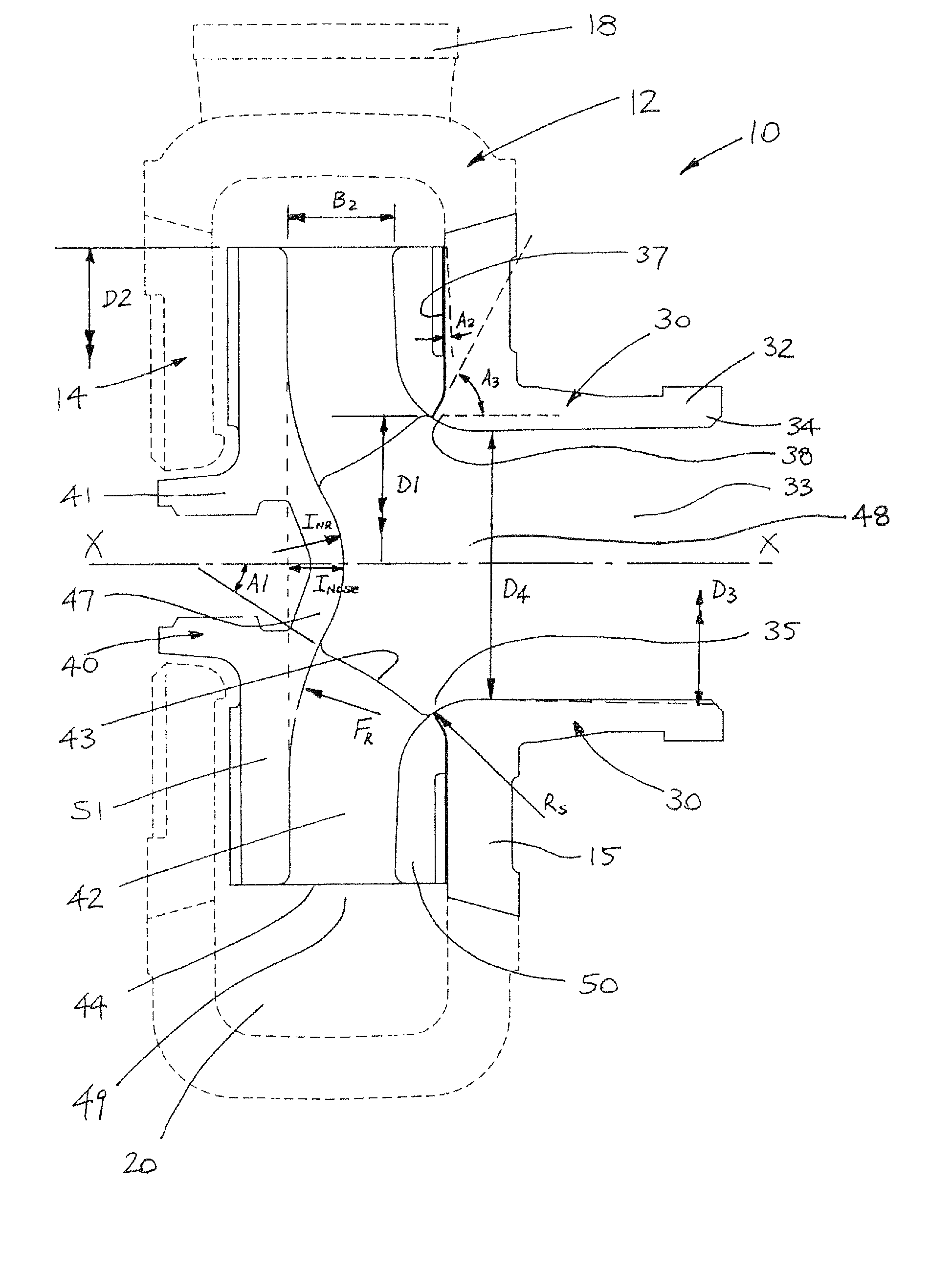
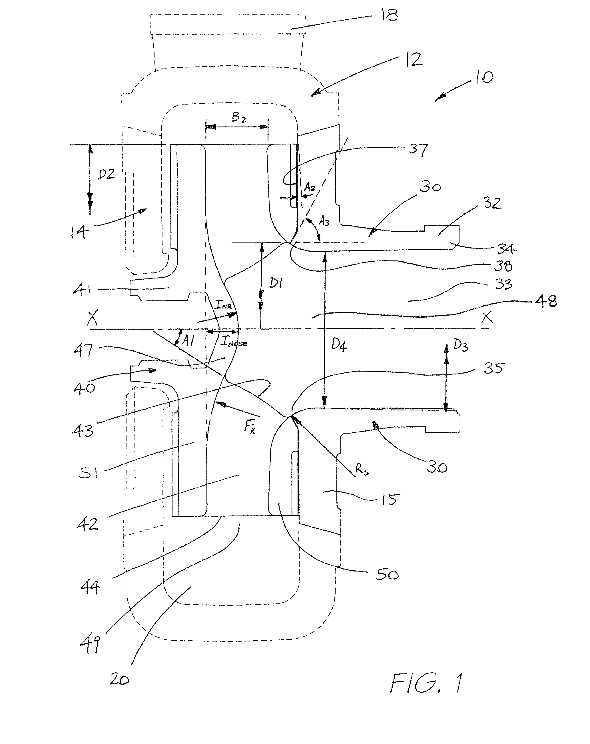
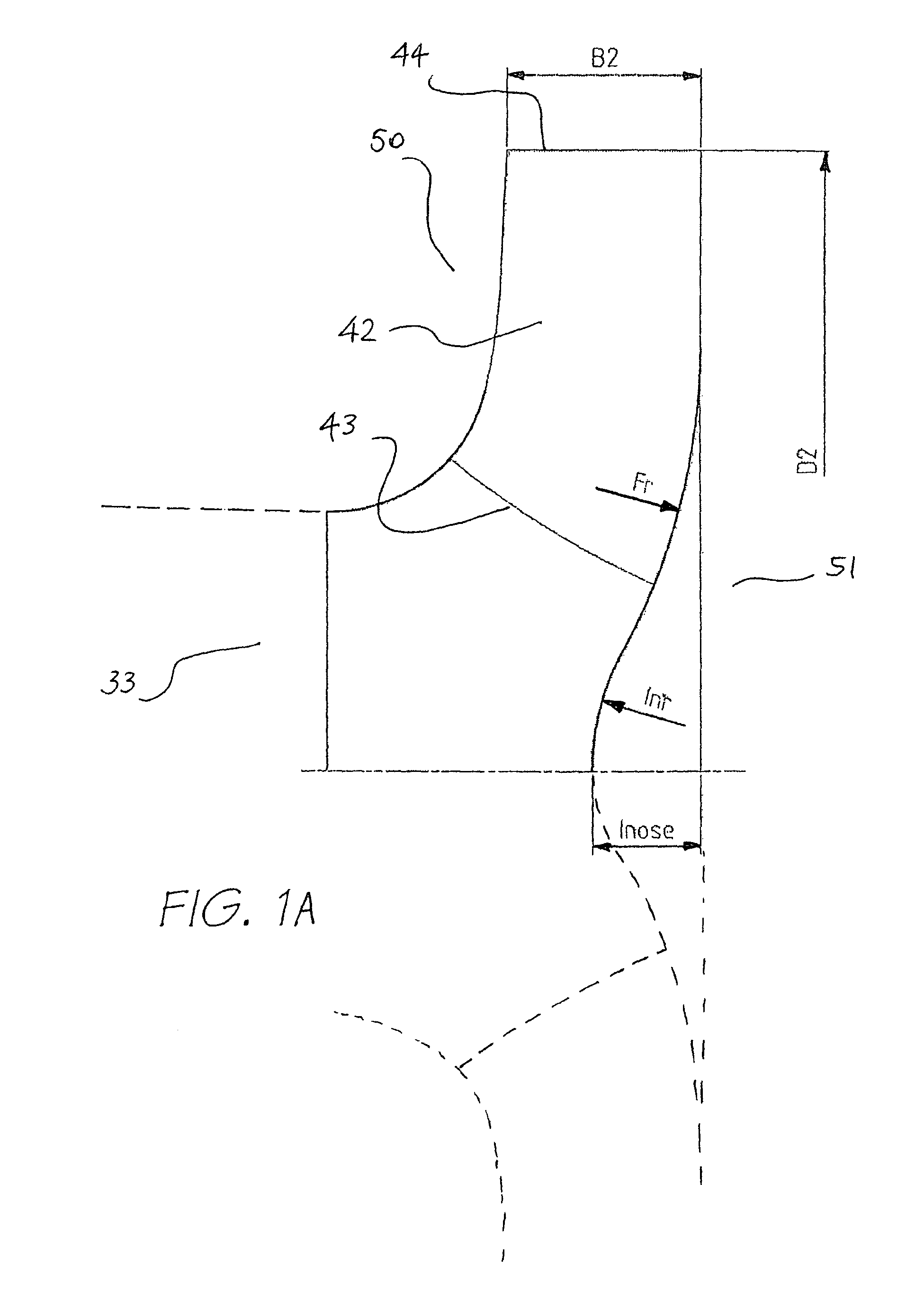
A centrifugal pump impeller includes front and back shrouds and a plurality of pumping vanes therebetween, each pumping vane having a leading edge in the region of an impeller inlet and a trailing edge, the front shroud has an arcuate inner face in the region of the impeller inlet, the arcuate inner face having a radius of curvature (Rs) in the range from 0.05 to 0.16 of the outer diameter of the impeller (D2) The back shroud includes an inner main face and a nose having a curved profile with a nose apex in the region of the central axis which extends towards the front shroud, there being a curved transition region between the inner main face and the nose. Fr is the radius of curvature of the transition region and the ratio Fr / D2 is from 0.32 to 0.65. Other ratios of various dimensions of the impeller are also described.

Description

BACKGROUND OF THE INVENTION[0001]1. Technical Field[0002]This disclosure relates generally to centrifugal pumps and more particularly though not exclusively to pumps for handling abrasive materials such as for example slurries and the like.[0003]2. Background Art[0004]Centrifugal slurry pumps, which may typically comprise hard metal or elastomer liners and / or casings that resist wear, are widely used in the mining industry. Normally, the higher the slurry density, or the larger or harder the slurry particles, will result in higher wear rates and reduced pump life.[0005]Centrifugal slurry pumps are widely used in minerals processing plants from the start of the process where the slurry is very coarse with associated high wear rates (for example, during milling), to the end of the process where the slurry is very much finer and the wear rates greatly reduced (for example, when flotation tailings are produced). As an example, slurry pumps dealing with a coarser particulate feed duty ma...

Claims


Application Information

Patent Timeline
Patent Type & Authority Patents(United States)
IPC IPC(8): F04D29/22
CPCF04D29/167F01D5/143F04D29/2288F04D29/2255F04D29/22F04D29/242F04D7/04Y10S416/02F04D1/04
Inventor BURGESS, KEVIN EDWARDLIU, WEN-JIELAVAGNA, LUIS MOSCOSO
Owner WEIR MINERALS AUSTRALIA LTD
Learn More