Over-current protection device

a protection device and overcurrent technology, applied in the direction of resistor manufacture, current responsive resistors, varistors, etc., can solve the problems of less uniform dispersion, poor adhesion of ceramic powder to polyolefin polymer, easy accumulation of filler particles, etc., to increase flame retardant capability, increase material hardness, water or air permeation

Inactive Publication Date: 2012-06-12
POLYTRONICS TECH
View PDF6 Cites 12 Cited by
  • Summary
  • Abstract
  • Description
  • Claims
  • Application Information

AI Technical Summary

Benefits of technology

[0008]The present invention provides an over-current protection device. By adding a conductive nickel filler, a non-conductive metal nitride filler with certain particle size distribution, and least one crystalline polymer with a low melting point, the over-current protection device exhibits low resistance, fast tripping at a lower temperature, high voltage endurance and resistance repeatability. The present invention further provides a packaging material layer having epoxy resin, so as to increase anti-oxidation and reduce water or air permeation to the device.

Problems solved by technology

If the metal particles are used as the conductive fillers, their larger specific weight results in a less-uniform dispersion.
For example, nickel fillers exhibit weak magnetism, so the filler particles accumulate easily and are not easily dispersed.
Moreover, since the ceramic powder lacks a rough surface like carbon black and has no obvious chemical function groups, the ceramic powder exhibits poor adhesion with the polyolefin polymer, compared to the adhesion of the carbon black to the polyolefin polymer, and consequently, the resistance repeatability of the PTC conductive material is not easy to control.

Method used


Image

  • Over-current protection device
  • Over-current protection device
  • Over-current protection device

Examples


Embodiment Construction

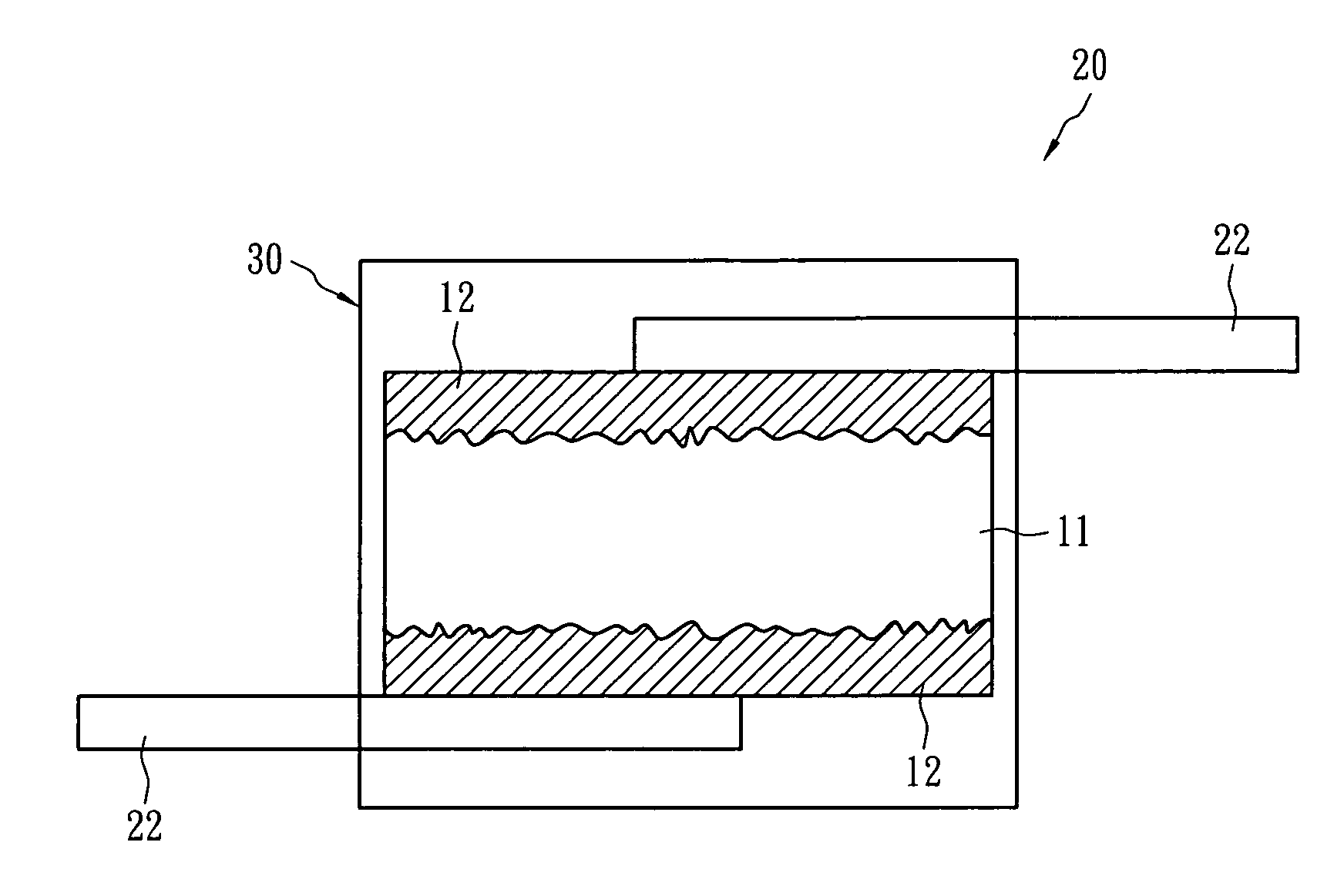
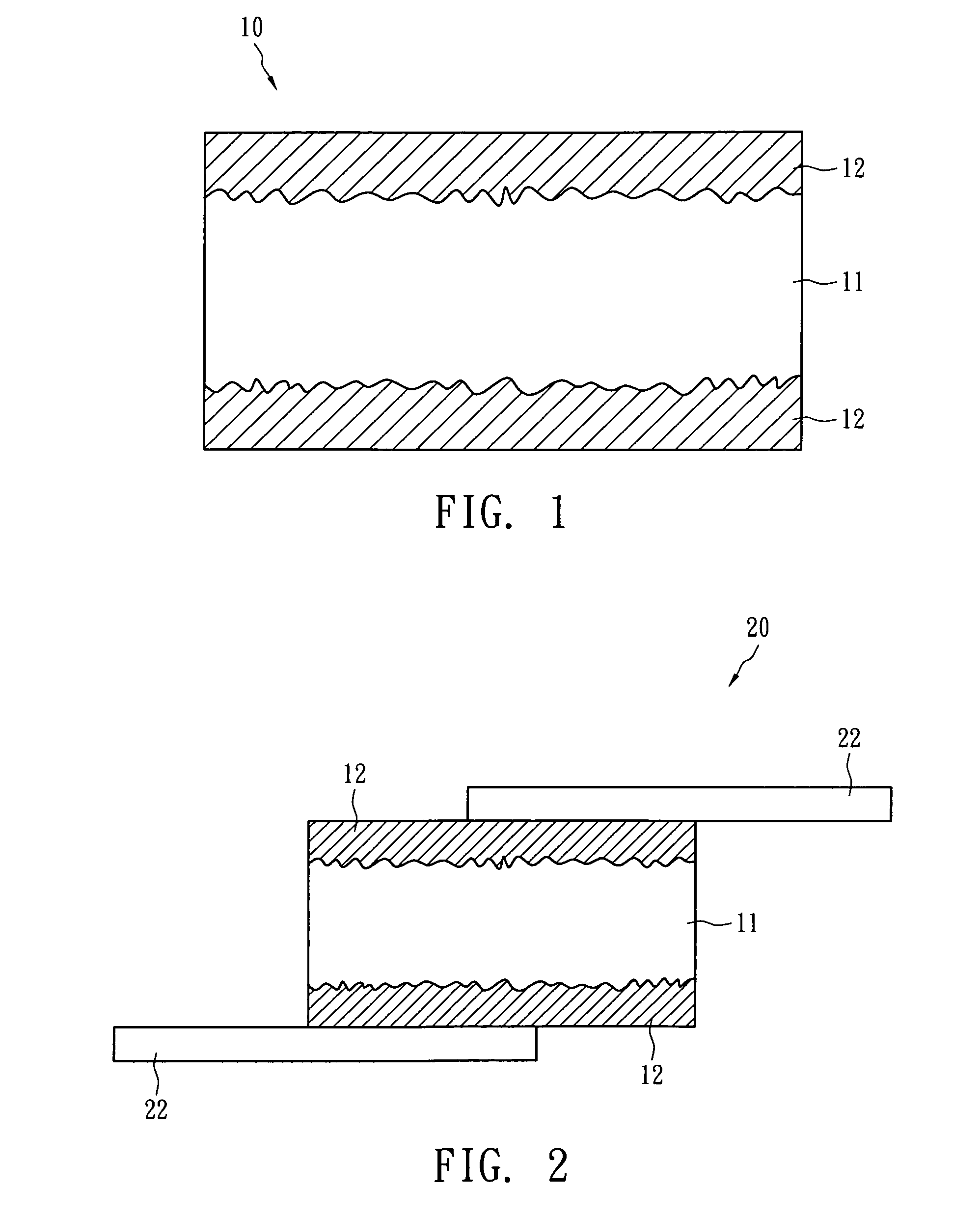
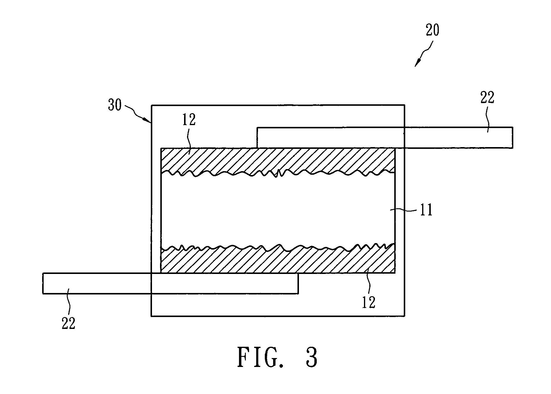
[0022]The following describes the compositions of Example I, Example II, Example III, Example IV, Comparative Example 1 and Comparative Example 2 and the manufacturing processes of the over-current protection device of the present invention with accompanying figures.

[0023]The composition and weight (in grams) of the PTC material layer in the over-current protection device of the present invention are shown in Table 1 below.

[0024]

TABLE 1LDPE-1HDPE-1HDPE-2CarbonComposition(g)(g)(g)BN (g)AlN (g)Si3N4 (g)Black (g)Ni (g)Example I8.516.5—5  ———160Example II8.2—17.64.4———156Example III 8.516.5——5.2——160Example IV8.217.6——5.4—160Comparative —8.110.2————150Example 1Comparative —9.2 9.73.6——33—Example 2

[0025]In Table 1, LDPE-1 is a low-density crystalline polyethylene (density: 0.924 g / cm3; melting point: 113° C.); HDPE-1 as a high-density polyethylene (density: 0.943 g / cm3; melting point: 125° C.); HDPE-2 is a high-density polyethylene (density: 0.961 g / cm3; melting point: 131° C.); boron ni...


PUM

PropertyMeasurementUnit
melting pointaaaaaaaaaa
particle sizeaaaaaaaaaa
thicknessaaaaaaaaaa

Abstract

An over-current protection device comprises two metal foils, a positive temperature coefficient (PTC) material layer and a packaging material layer. The PTC material layer is sandwiched between the two metal foils and has a volume resistivity below 0.1 Ω-cm. The PTC material layer includes (i) plural crystalline polymers having at least one crystalline polymer with a melting point less than 115° C.; (ii) an electrically conductive nickel filler having a volume resistivity less than 500 μΩ-cm; and (iii) a non-conductive metal nitride filler. The electrically conductive nickel filler and non-conductive metal nitride filler are dispersed in the crystalline polymer. The packaging material layer which encapsulates the chip is essentially comprised of the PTC layer and the two metal foils. The packaging material layer is formed by reacting epoxy resin with a hardener having amide functional group.

Description

BACKGROUND OF THE INVENTION[0001]1. Field of the Invention[0002]The present invention relates to an over-current protection device.[0003]2. Description of the Prior Art[0004]The resistance of PTC conductive material is sensitive to temperature change. Due to such property, the PTC conductive material can be used as current-sensing material and has been widely used in over-current protection devices and circuits. The resistance of the PTC conductive material remains low at room temperature so that the over-current protection device or circuit can operate normally. However, if an over-current or an over-temperature event occurs, the resistance of the PTC conductive material immediately increases to a high-resistance state (over 102 ohm). Therefore, the excessive, current is blocked and the objective of protecting the circuit elements or batteries is achieved.[0005]In general, the PTC conductive material contains one or more crystalline polymers and a conductive filler. The conductive ...

Claims


Application Information

Patent Timeline
Patent Type & Authority Patents(United States)
IPC IPC(8): H01C7/10
CPCH01C7/027H01C17/06553H01C17/06586
Inventor SHA, YI ANLO, KUO CHANGYANG, CHIN PIAO
Owner POLYTRONICS TECH
Why Eureka
Try Eureka