
Current sink system based on sample and hold for source side sensing

a current sink and source side sensing technology, applied in the field of sensing data in memory devices, can solve the problems of increasing the complexity the noise of the sense amplifier, and the time needed for sensing, so as to reduce the amount of voltage variations, reduce the variation of read current, and tighten the distribution of voltage or current on the sensing node among memory cells in the array.

Active Publication Date: 2012-04-03
MACRONIX INT CO LTD
View PDF17 Cites 9 Cited by
  • Summary
  • Abstract
  • Description
  • Claims
  • Application Information

AI Technical Summary

Benefits of technology

[0024]Using the difference between the read current and the sink current, rather than the entire read current, reduces the amount of voltage variations at the source terminal of the memory cell during the sensing operation. This in turn reduces the variation in the read current among cells in the array during source-side sensing. As a result, the distribution in the voltage or current on the sensing node among memory cells in the array will be tightened.

Problems solved by technology

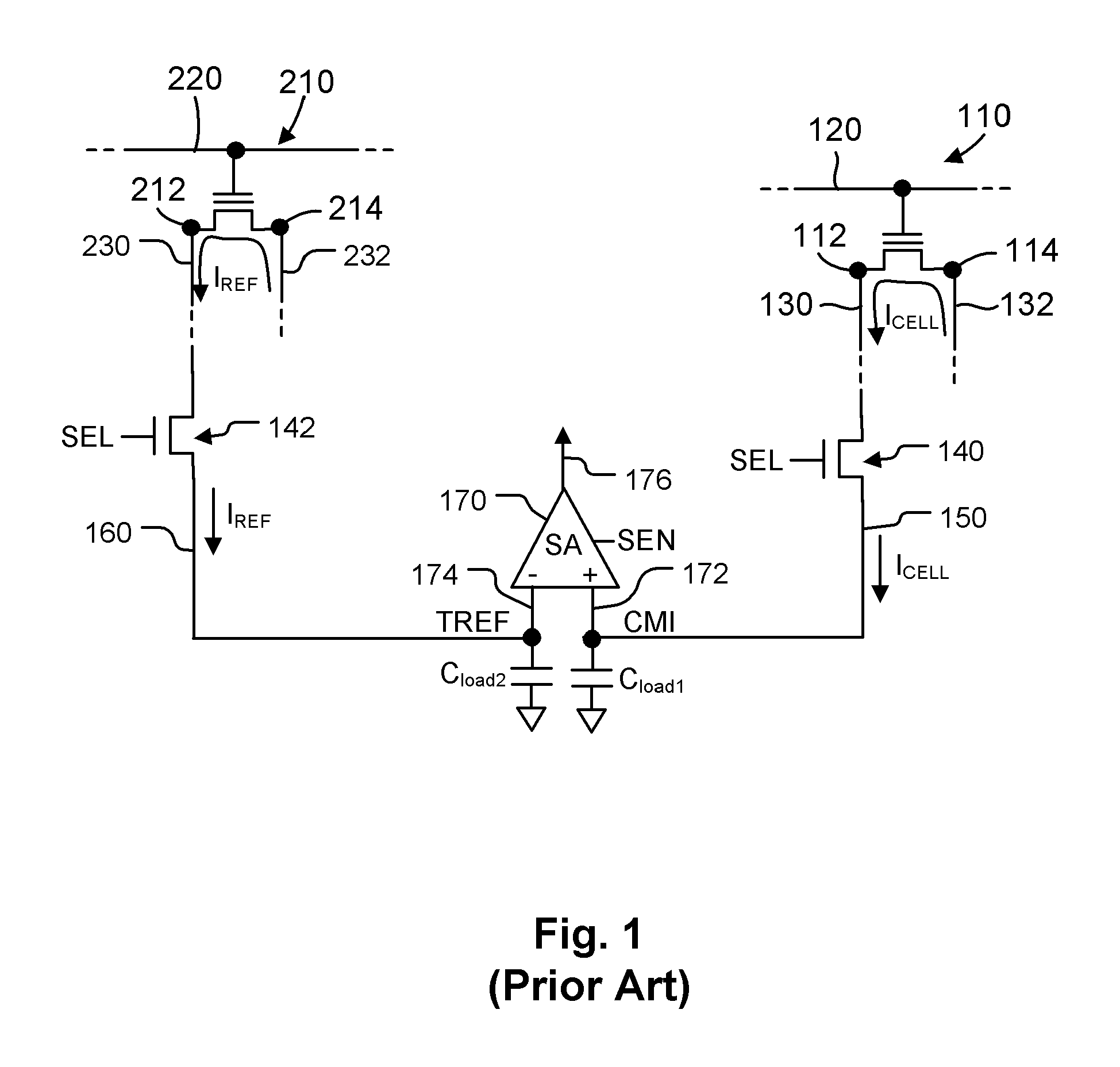
An issue which arises during the sensing operation is the susceptibility of the sense amplifier 170 to noise.
Specifically, noise occurring during the sensing operation can affect the difference between the voltages on the sensing input 172 and the reference input 174, which increases complexity of the sense amplifier 170 or the time needed for sensing.
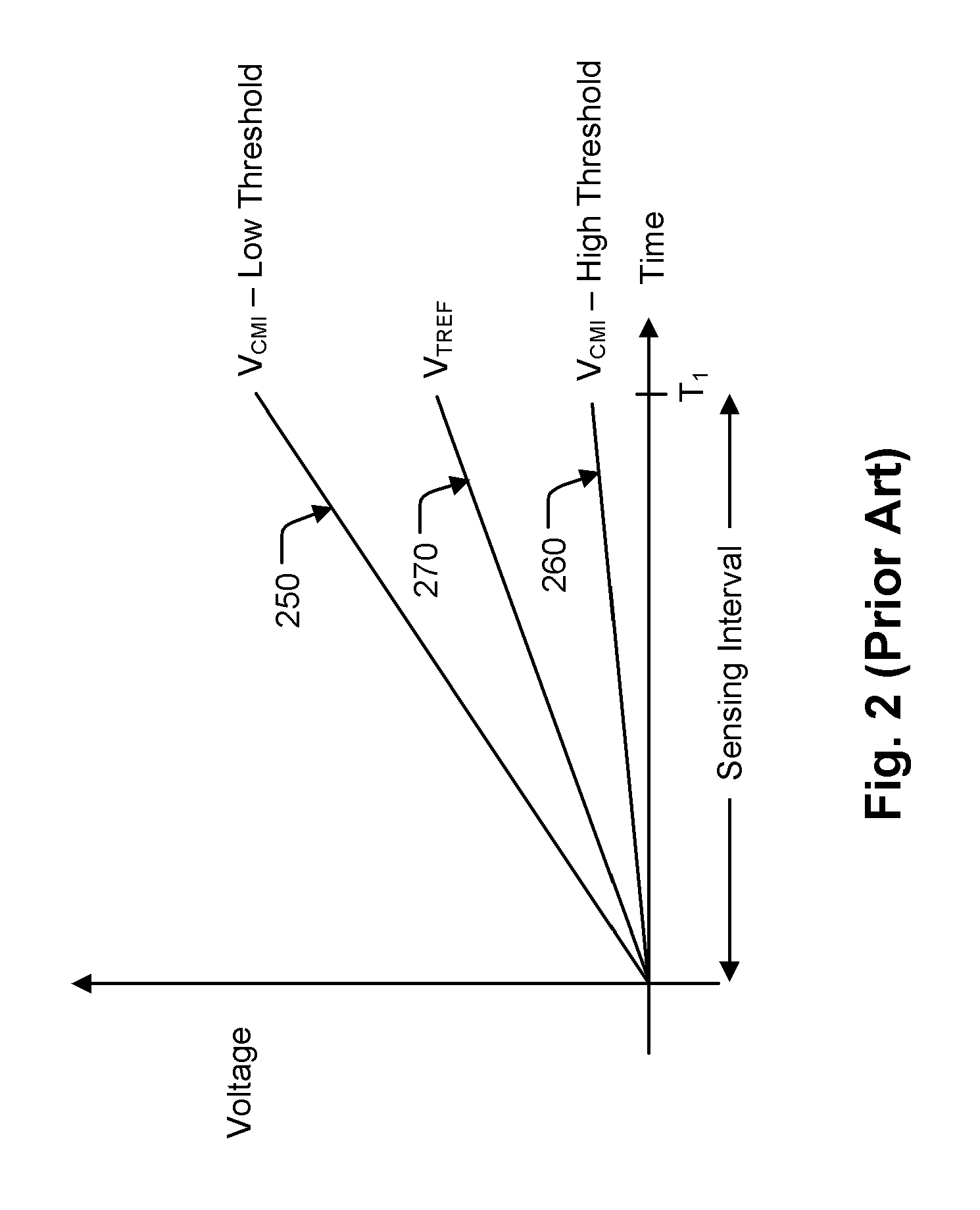
These variations result in differences in read current among memory cells storing the same data value, including differences in the change in read current caused by an increase in the source voltage.
Thus, having the source voltage increase by an amount dependent upon the read current results in a wide distribution of the voltage or current at the sensing input 172 of the sense amplifier 170, which increases the complexity of the sense circuitry or the time needed for sensing.

Method used


Image

  • Current sink system based on sample and hold for source side sensing
  • Current sink system based on sample and hold for source side sensing
  • Current sink system based on sample and hold for source side sensing

Examples


first embodiment

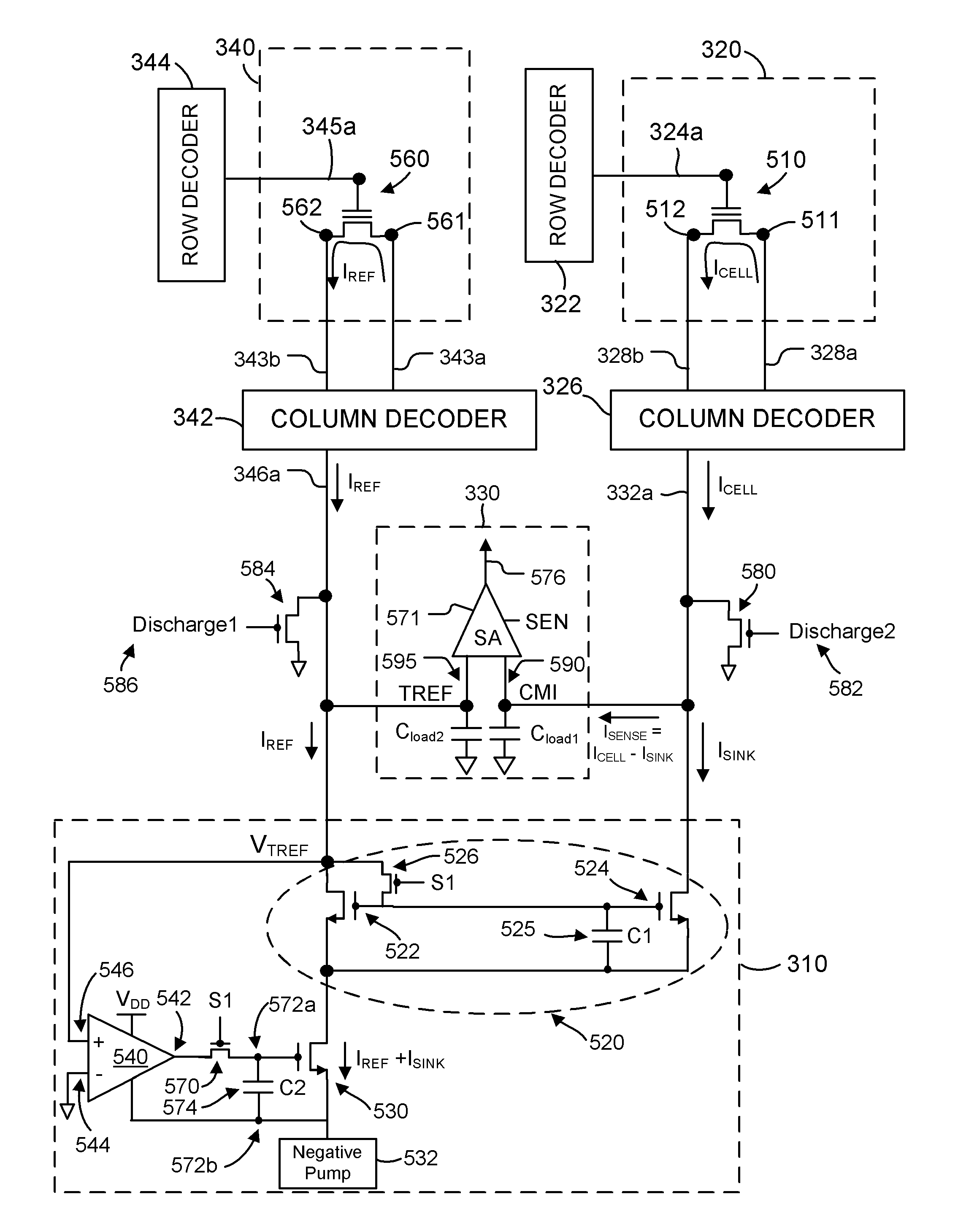
[0055]FIG. 5 is a schematic diagram of the sample and hold current sink circuitry 310 used for sensing a data value stored in a selected memory cell 510 in the memory array 320.

[0056]Word line 324a is coupled to the gate terminal of the memory cell 510. Bit lines 328a, 328b are coupled to the drain and source terminals 511, 512 of the memory cell 510.

[0057]In a sense operation of the memory cell 510, appropriate voltages are applied to word line 324a and bit line 328a to induce a read current ICELL from the drain 511 to the source 512 and onto the bit line 328b. The read current ICELL is provided to the data line 332a via column decoder 326.

[0058]In the illustrated example, reference cell 560 of the reference array 340 is used to provide the reference current IREF. Word line 345a is coupled to the gate terminal of the reference cell 560. Bit lines 343a and 343b are coupled to the drain terminal 561 and source terminal 562 of the reference cell 560.

[0059]Voltages are applied to the w...

second embodiment

[0098]FIG. 7 is a schematic diagram of the sample and hold current sink circuitry 310. In FIG. 7, the load transistor 530 is implemented as a PMOS transistor. The positive input 546 of the operational amplifier 540 is coupled to ground, and the negative input 544 is coupled to the reference line 346a so that a negative feedback path can be established between the output 542 and the negative input 544.

third embodiment

[0099]FIG. 8 is a schematic diagram of the sample and hold current sink circuitry 310. In FIG. 8, the gate terminal of the transistor 522 is selectively coupled to ground by switch 526. Using the switch 526 coupled to ground rather than the input 546 of the operational amplifier 540 can improve the closed loop response time by reducing the capacitance coupled to the reference line 346a.


PUM


Abstract

Source-side sensing techniques described herein determine the data value stored in a memory cell based on the difference in current between the read current from the source terminal of the memory cell and a sink current drawn from the read current. The sink current is drawn in response to a magnitude of an operating voltage between first and second nodes. During a first time interval, the operating voltage is set in response to a magnitude of the reference current using a feedback path. During a second time interval following the first time interval, the operating voltage is held independent of the feedback path. The data value stored in the memory cell is determined based on a difference in current between the read current and the sink current during the second time interval.

Description

REFERENCE TO RELATED APPLICATIONS[0001]This application is related to U.S. patent application Ser. No. 12 / 576,466, filed 9 Oct. 2009, entitled “Current Sink System for Source Side Sensing,” which is incorporated by reference as if fully set forth herein.BACKGROUND OF THE INVENTION[0002]1. Field of the Invention[0003]The present invention relates to sensing data in memory devices, and more particularly to preventing disturbance of sensing operations in memory devices due to noise.[0004]2. Description of Related Art[0005]There are a variety of types of non-volatile memory based on charge storage memory cells, including memory cells that store charge between the channel and gate of a field effect transistor. The amount of charge stored affects the threshold voltage of the transistor, which can be sensed to indicate data.[0006]One type of charge storage memory cell is known as a floating gate memory cell. In a floating gate memory cell, charge is stored on an electrically conductive lay...

Claims


Application Information

Patent Timeline
Patent Type & Authority Patents(United States)
IPC IPC(8): G11C16/06
CPCG11C7/02G11C16/06G11C7/062G11C16/28G11C2207/063G11C7/067G11C2013/0054G11C13/004
Inventor LIAO, KUO-YUCHEN, HAN-SUNGHUNG, CHUN-HSIUNG
Owner MACRONIX INT CO LTD
Learn More