Resist pattern thickening material and process for forming resist pattern, and semiconductor device and method for manufacturing the same

a technology of resist pattern and thickening material, which is applied in the direction of photosensitive materials, instruments, photomechanical equipment, etc., can solve the problems of difficult development of new resist materials suitable for exposure light of shorter wavelengths, reducing the wavelength of exposure light, and requiring a great deal of cost, etc., to achieve excellent, uniform resist pattern-thickening effect, and exceed exposure limit. , the effect of fine structur

Inactive Publication Date: 2012-03-06
FUJITSU LTD
View PDF55 Cites 3 Cited by
  • Summary
  • Abstract
  • Description
  • Claims
  • Application Information

AI Technical Summary

Benefits of technology

[0018]When the resist pattern thickening material is applied over the resist pattern, the resist pattern thickening material infiltrates the resist pattern at their interface to interact (mix) with the resist pattern material. At this point the resist pattern thickening material has excellent compatibility with the resist pattern and thus results in efficient formation of a surface layer (mixing layer), a layer in which the resist pattern thickening material and the resist pattern are mixed, on the surface of the resist pattern which now serves as an inner layer. In this way the resist pattern is efficiently thickened by means of the resist pattern thickening material. The resist pattern thus thickened (hereinafter referred to as “swelled” in some cases) in this way has been uniformly thickened by means of the resist pattern thickening material (hereinafter such a resist pattern may be referred to as “thickened resist pattern” in some cases). Thus, a space pattern formed using the thickened resist pattern has a fine structure, exceeding the exposure (resolution) limits. It should be noted that the resist pattern thickening material of the present invention contains a compound which is represented by the general formula (1) and has a carboxyl group, and thus exhibits an excellent, uniform resist pattern-thickening effect regardless of the type of the resist pattern material, resist pattern size or the like, which means that such an effect is less dependent on the type of the resist pattern material, resist pattern size or the like. In addition, compounds represented by the general formula (1) have a moiety having a cyclic structure, thereby imparting the resist pattern thickening material of the present invention with excellent etching resistance. For these reasons, the resist pattern thickening material of the present invention can be suitably used for the formation of such resist patterns as line-patterns, which are adopted in the interconnection layers of LOGIC LSIs provided with resist patterns of various sizes.
[0020]In this process for forming a resist pattern a resist pattern is formed, and the resist pattern thickening material of the present invention is then applied thereon, whereby the resist pattern thickening material infiltrates the resist pattern at their interface to interact (mix) with the resist pattern material, leading to the formation of a surface layer (mixing layer), a layer in which the resist pattern thickening material and the resist pattern are mixed, on the surface of the resist pattern which in turn serves as an inner layer. In this way the resist pattern is uniformly thickened by means of the resist pattern thickening material. Thus, the space pattern formed using the thickened resist pattern has a fine structure, exceeding the exposure (resolution) limits. It should be noted that the resist pattern thickening material of the present invention contains a compound which is represented by the general formula (1) and has a carboxyl group, and thus exhibits an excellent, uniform resist pattern-thickening effect regardless of the type of the resist pattern material, resist pattern size, or the like, which means that such an effect is less dependent on the type of the resist pattern material, resist pattern size or the like. In addition, compounds represented by the general formula (1) have a moiety having a cyclic structure, thereby imparting the resist pattern thickening material of the present invention with excellent etching resistance. For these reasons, the resist pattern thickening material of the present invention can be suitably used for the formation of such resist patterns as line-patterns, which are adopted in the interconnection layers of LOGIC LSIs provided with not only contact hole patterns, but also resist patterns of various sizes.
[0023]Subsequently, by etching the surface of the workpiece using the thickened resist pattern as a mask, the surface of the workpiece is patterned finely and precisely with accurate dimension, whereby high-quality, high performance semiconductor devices having fine, precise interconnection patterns with accurate dimension can be produced efficiently.
[0024]The semiconductor device of the present invention is manufactured by the process of the present invention for manufacturing a semiconductor device. The semiconductor device has fine, precise patterns including interconnection patterns with accurate dimension, and is of high quality and performance.

Problems solved by technology

However, reducing the wavelength of exposure light requires improvement of exposure devices, which requires a great deal of cost.
Further, the development of new resist materials suitable for exposure light of shorter wavelength is not easy.
The RELACS technique, however, has the following problems: The KrF resist to be used is formed of an aromatic resin composition such as novolac resin and naphthoquinonediazide resin, and therefore, while aromatic rings contained in the aromatic resin composition allows KrF excimer laser light (wavelength: 248 nm) to pass through it, they absorb ArF (argon fluoride) excimer laser light (wavelength: 193 nm), which has a shorter wavelength than KrF excimer laser light, thereby preventing it from passing through the aromatic resin composition.
Moreover, the RELACS technique also has a problem that although the resist swelling material is effective for thickening or swelling of the KrF resist, it is not suitable for thickening or swelling of the ArF resist.
In addition, the resist swelling agent itself has poor etching resistance.
Thus, if the ArF resist pattern, which has poor etching resistance, is intended to be thickened (swelled), it is impossible to form a pattern with the same shape as the swelled pattern on the substrate.
Even when the KrF resist pattern, which has relatively excellent etching resistance, is intended to be thickened (swelled), it is impossible to perform precise etching in a case where, for example, the etching conditions are stringent, where the substrate is thick, where the KrF resist pattern is fine, and where a resist film is thin, leading to the problem that a pattern with the same shape as the swelled pattern cannot be obtained.
When x-ray or electron beam having a wavelength shorter than ArF excimer laser light is used for pattern forming, however, it results in high cost and low productivity.

Method used


Image

  • Resist pattern thickening material and process for forming resist pattern, and semiconductor device and method for manufacturing the same
  • Resist pattern thickening material and process for forming resist pattern, and semiconductor device and method for manufacturing the same
  • Resist pattern thickening material and process for forming resist pattern, and semiconductor device and method for manufacturing the same

Examples


example 1

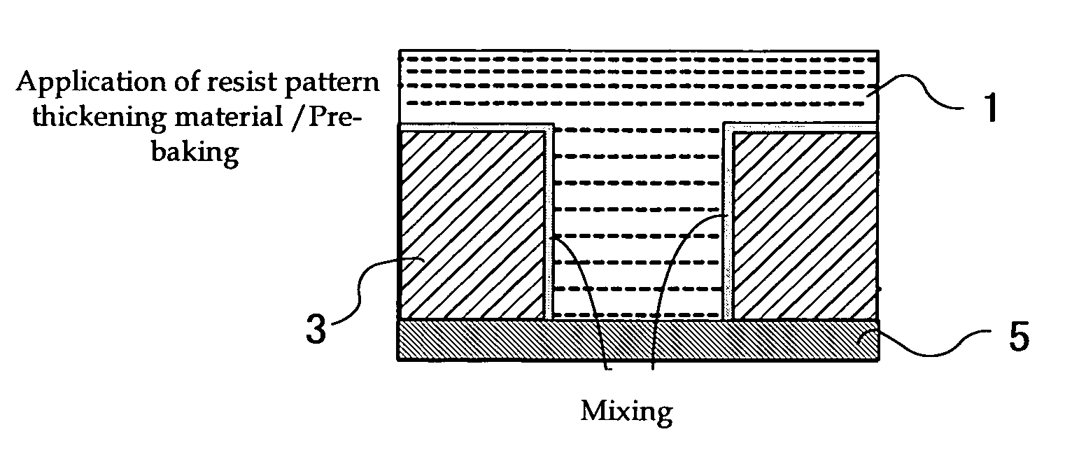
—Preparation of Resist Pattern Thickening Materials—

[0136]Resist pattern thickening materials A to O having compositions shown in Table 1 were prepared.

[0137]Note in Table 1 that the term “thickening material” means a resist pattern thickening material and that the letters “A” to “O” correspond to the resist pattern thickening materials A to O. Out of the resist pattern thickening materials A to O, the resist pattern thickening materials M to O were those prepared in Comparative Example and the resist pattern thickening materials A to L were those prepared in Examples of the present invention. In Table 1 the units in parentheses represent “parts by mass (g).”

[0138]Phenylalanine, phenyllactic acid, phenylglycine and 1-methyl-cyclohexylcarboxylic acid, which are listed in the “Compound Represented by the General Formula (1)” column for the resist pattern thickening materials A to L, are all compounds represented by the following general formula (1):

[0139]

where R represents a moiety ha...

example 2

[0155]As shown in FIG. 9, the interlayer dielectric film 12 was formed on a silicon substrate 11 and as shown in FIG. 10, a titanium film 13 was formed on the interlayer dielectric film 12 by sputtering. Next, as shown in FIG. 11, a resist pattern 14 was formed by a known photolithographic technique. Using the resist pattern 14 as a mask, the titanium film 13 was patterned by reactive ion etching to form an opening 15a. Subsequently, reactive ion etching was performed to remove the resist pattern 14 and, at the same time, as shown in FIG. 12, an opening 15b was formed in the interlayer dielectric film 12 using the titanium film 13 as a mask.

[0156]Next, the titanium film 13 was removed in a wet processing and as shown in FIG. 13, a TiN film 16 was formed on the interlayer dielectric film 12 by sputtering. By electrolytic plating, a Cu film 17 was then deposited on the TiN film 16. As shown in FIG. 14, the surface of the silicon substrate 11 was then planarized by removing the barrier...


PUM

PropertyMeasurementUnit
wavelengthaaaaaaaaaa
temperatureaaaaaaaaaa

Abstract

The present invention provides a resist pattern thickening material, which can utilize ArF excimer laser light; which, when applied over a resist pattern such as an ArF resist having a line pattern or the like, can thicken the resist pattern regardless of the size of the resist pattern; which has excellent etching resistance; and which is suited for forming a fine space pattern or the like, exceeding the exposure limits. The present invention also provides a process for forming a resist pattern and a method for manufacturing a semiconductor device, wherein the resist pattern thickening material of the present invention is suitably utilized.

Description

CROSS-REFERENCE TO RELATED APPLICATIONS[0001]This application is based upon and claims the benefits of the priority from the prior Japanese Patent Application No. 2005-345920, filed on Nov. 30, 2005, the entire contents of which are incorporated herein by reference.BACKGROUND OF THE INVENTION[0002]1. Field of the Invention[0003]The present invention relates to a resist pattern thickening material that enables formation of a fine space pattern by thickening a resist pattern formed upon manufacturing of a semiconductor device, while exceeding the exposure (resolution) limits of the light sources of available exposure devices, to a process for forming a resist pattern, to a semiconductor device, and to a method for manufacturing the semiconductor device, by utilizing the resist pattern thickening material.[0004]2. Description of the Related Art[0005]In recent years the increase in the packing density of semiconductor integrated circuits has put LSIs and VLSIs to practical use. In keepi...

Claims


Application Information

Patent Timeline
Patent Type & Authority Patents(United States)
IPC IPC(8): G03F7/004G03F7/085
CPCG03F7/40H01L21/0273H01L21/76816G03F7/168
Inventor KOZAWA, MIWANOZAKI, KOJI
Owner FUJITSU LTD
Why Eureka
Try Eureka